"PaperLaul's Terminator 2: Hunter Killer Aerial - by DanBKing"

Status
Not open for further replies.

DanBKing

Dan the Man
Feb 29, 2012
1,817
1,587
113
Netherlands

Sky Seeker

Well Established Member
Jun 1, 2015
1,178
1,083
95
Shut the Gate....!!

I will let you know of the outcome ....... :nailbiting::nailbiting:

:wave:

Dan,

This is quite useful for those of us that are "electrically challenged" (uh ok forget the pc - electronic idiots).

Thanks for sharing.

Time to learn and get out of the idiot box!

Sky Seeker
 
  • Like
Reactions: Tonino and DanBKing

DanBKing

Dan the Man
Feb 29, 2012
1,817
1,587
113
Netherlands
We're like two peas in a pod. Pity the pod. ~ James St. James

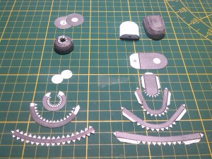
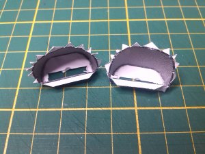
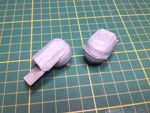
As the model has four legs and cannot stand on only two, I made up the forward leg mounting pods.
I needed to get these finalized and work out the manner in which I am going to mount them to the fuselage and the frame, before finally gluing the frame into the fuselage.

The parts were made up in a similar manner to the rear pods .....

IMG_20151219_130334.jpg

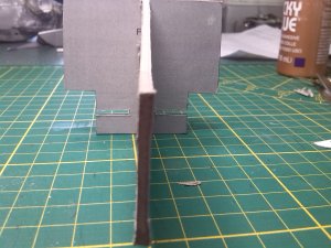
I glued a thick piece of cardboard on the inside of the bottom plate that extended about 20mm out of the end of the pod.
The mounting holes for the shaft for the leg attachment were punched out and the shaft of the pods was then inserted and held in place by a ring of card.
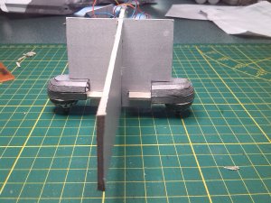
I then cut slots in the fuselage mounting points and also lined everything up and then cut slots in the frame piece.

IMG_20151206_133538.jpg IMG_20151221_122521.jpg

And a test fit.....

IMG_20151221_122410.jpg

Once I was happy with everything, I gave the pod assemblies a rough sanding and a bit of filler here and there and gave them a thick coat of primer.
I need to do more finishing and smoothing on them yet, but they are getting there ;)

IMG_20160102_125548.jpg

Now that the pods were finalized I could glue the internal frame permanently into the fuselage.
Everything is now sitting drying.

I'll hopefully be back with a small update later.

:wave:
 

Tonino

Well-Known Member
Apr 15, 2004
791
1,775
83
61
Republic of San Marino
www.facebook.com
You're a continuous source of inspiration. :)
This is an interesting topic: a cardmodel as a "base" to obtain smooth surfaces using filler (and painting all over).
What kind of filler did you use?
Did you use it as it is or you added some kind of thinner to make it more "fluid"?
 
  • Like
Reactions: DanBKing

DanBKing

Dan the Man
Feb 29, 2012
1,817
1,587
113
Netherlands
Thanks @Tonino

The filler I use, I buy at the local 'Euro Shop' (or 'dollar store', if you prefer.)
It costs next to nothing for 400g of the stuff. It is water based and comes ready to use from the tube.
I tend to just slap it on from the tube, wait 10 minutes and then smooth it out with a dampened finger.
It can be thinned out with a drop of water or two first, but I very rarely do that.
It can be given an initial light sanding after about 1/2 hour and it turns rock hard after about an hour........

General_744.JPG
 
  • Like
Reactions: Tonino

zathros

*****SENIOR ADMINISTRATOR*****
Staff member
Administrator
Moderator
Apr 5, 2013
13,498
9,549
228
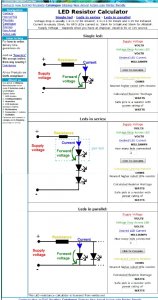
@Tonino,, use this page to make series, parallel, series-parallel circuits. This page makes it very easy to calculate such a circuit. You can select where you want the LED's to go and this page (LED Calculator) will show you what you need to make the circuit. LED's come with the information printed on the package, such as the forward voltage(Voltage Drop) needed to turn it on, etc. :)

Link = http://www.hebeiltd.com.cn/?p=zz.led.resistor.calculator

Page looks like this, user friendly:

12345.jpg
 

Tonino

Well-Known Member
Apr 15, 2004
791
1,775
83
61
Republic of San Marino
www.facebook.com
Very interesting! I'm a lotta curious to see it shining in the night. I trust - for this - on your photo abilities (that you showed us so well when you depicted your Discovery like in real set picture).

I still need to understand just one thing: as I see in the LED calculator page, you input some data and receive as output the kind of resistor to put in the circuit. Some data are fixed (the voltage supplied and the voltage drop across LEDs) as they depends, respectively, on power source and kind of LEDs you have, right? But how do you choose desired LED current (third data to input)?
If I should set some kind of project for a model lighting, I just have no idea of the quantity of milliamps to put in that field...
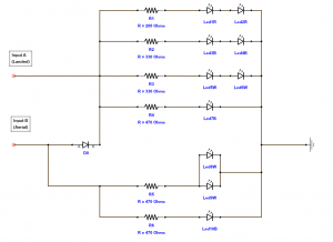
I see you used different resistors in your circuit. What is the criteria?
 

DanBKing

Dan the Man
Feb 29, 2012
1,817
1,587
113
Netherlands
As a general rule of thumb: When using high intensity LED's, the following data is relevant......

White or Blue: Voltage drop: 3V @ 20mA
Red, Green: Voltage drop 2V @ 20mA

For high intensity LED's the current is nearly always 20mA.... See below .....


How to Work With 3mm and 5mm LEDs
Most LEDs have their characteristics specified at a current of 20 mA. If you want really good reliability and you are not certain you don't have worse-than-average heat conductivity in your mounting, heat buildup in wherever you mount them, voltage/current variations, etc. then design for 15 milliamps.

Now for how to make 15 milliamps flow through the LED:

First you need to know the LED voltage drop. It is safe enough to assume 1.7 volts for non-high-brightness red, 1.9 volts for high-brightness, high-efficiency and low-current red, and 2 volts for orange and yellow, and 2.1 volts for green. Assume 3.4 volts for bright white, bright non-yellowish green, and most blue types. Assume 4.6 volts for 430 nM bright blue types such as Everbright and Radio Shack. Design for 12 milliamps for the 3.4 volt types and 10 milliamps for the 430 NM blue.

Source: http://www.theledlight.com/LED101.html
 

DanBKing

Dan the Man
Feb 29, 2012
1,817
1,587
113
Netherlands
@Tonino With regards to the different resistor values in my circuit...........

In the R1/Led1/Led2 combination:
Both Leds are red, so the voltage drop over each Led is 2V.
The Led's are in series, so the voltage drop across both Led's is 2V + 2V = 4V @ 20mA
Therefore using Ohms Law R=V/I: R = 4/0.02 = 200 ohms
In the R2/Led3/Led4 combination:
Both Leds are blue, so the voltage drop over each Led is 3V.
The Led's are in series, so the voltage drop across both Led's is 3V + 3V = 6V @ 20mA
Therefore using Ohms Law R=V/I: R = 6/0.02 = 300 ohms (Closest available resitor is 330 ohms)
Make sense ?????????? ;) ;)
 
Last edited:
  • Like
Reactions: Tonino

Revell-Fan

Co-Administrator
Staff member
Administrator
Moderator
Aug 1, 2009
11,609
12,349
228
Vreden
Nope. At 2mA the LED will hardly light up and 2mA are not 0.02 A. ;)
 

zathros

*****SENIOR ADMINISTRATOR*****
Staff member
Administrator
Moderator
Apr 5, 2013
13,498
9,549
228
Dan's right, on top of that page it states:

"
Voltage drop is usually 1.9~2.1V for AlGaInP, 3.1~3.5 for InGaN and 1.2V for Infrared.
Current is usualy 20mA, for UFO LEDs current is: 30mA for InGaN and 50mA for AlGaInP.
Supply Voltage - depends what you have at disposal. Usuall is 6V or 12V source. "

The milliamps should be written on the packaging, or can be looked up by the supplier, on that page is a lik to a Bazillion types of LED's that can provide that information.

Go to "http://ledz.com/" to find LED's and click on some, and you will see the specs right there, and their outcome. LED's use to be far simpler to use, but now you can make Billboard size Televisions with them, they have come a long way. Considering no one ever thought of making a clear diode, we could have had LED lighting back when thee first radios were made!! It was a Japanese scientists who theorized that there should be visible photons escaping from the anode and cathode gap. He sure was right! You may wish to order locally though!
 
  • Like
Reactions: Tonino

DanBKing

Dan the Man
Feb 29, 2012
1,817
1,587
113
Netherlands
“Electricity is really just organized lightning”~ George Carlin

It was time to get the lighting system circuitry installed and tested, before going any further......

I installed the tube that runs internally, between the engine mounts and cut a slot in the middle to allow me to run the associated engine wiring into the fuselage for connection to the circuit. I soldered the relevant resistors to the '+' leads of each LED. The bare wires and the resistors themselves were covered with heat-shrink to protect from electrical shorts. All the '-' leads were joined together and the wiring tidied up as best as possible. (Not that you are gonna see it anyway!) The wires running out of the engine mounts will be permanently connected to the engines, after the fuselage has been sprayed.
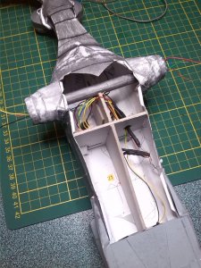
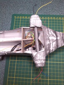
General_749.JPG General_750.JPG

Once I had triple checked everything with a continuity tester, I temporarily placed the nose in position and connected up the spotlights and the engines for the big test ......

I connected the power leads from the power supply into the engine power input plug. (This would be the 'landed' configuration, where the port engine and the spotlights are off.)

Again, I triple checked everything, and with fear and trepidation in my heart :nailbiting:, I plugged in the power supply ........
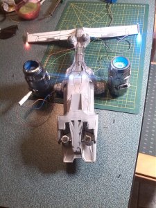
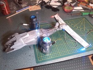
General_745.JPG General_746.JPG

PHEW!!!! Nothing blew up!!!! :D :D :D The lighting configuration is how it should be too...... :D:D

And for test 2, I then connected the power leads from the power supply into the fuselage input plug. (This would be the 'aerial' configuration, where all LEDs are on!)
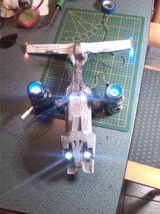
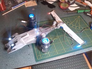
General_747.JPG General_748.JPG

YAHOOOOO!!! The diode 'gate' works perfectly. :animated:

Pity about the lens flare from the camera, but you get the general idea! :D :D

I'm pleased with that! Now I need to finalize the wiring and move on to the next stage .....

See y'all soon. :)

:wave:


.
 

Sky Seeker

Well Established Member
Jun 1, 2015
1,178
1,083
95
Sooo shiny! Nice job! Lighting really adds that extra dimension. thumbsup Trying to go for model of the month eh? You just might get it. Great work!

Sky Seeker
:tank:
 
  • Like
Reactions: DanBKing
Status
Not open for further replies.