On30 Disconnects

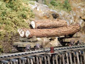
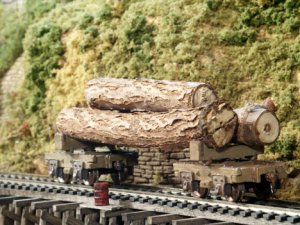
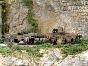
Here are some photos of a pair of On30 disconnected trucks that I put together from a Rusty Stumps kit. They were fairly easy to assemble, although some filing and test fitting of the parts was necessary. Actually, the assembly went faster than the painting and weathering. The "logs" were cut from the trunk of a sappling walnut tree that made the mistake of trying to come up in the middle of one of my flower beds. :rolleyes:
 

Attachments

  • disconnects38w.jpg
    disconnects38w.jpg
    64.8 KB · Views: 225

belg

Member
Apr 28, 2001
861
0
16
63
New Jersey USA
Visit site
Casey that is some more great modeling, I'm wondering if you have a picture of the truck before you put the wood on top. I wrote you the other day about how to make the double sided single truck, and am having a little trouble understanding the terminology.
 
Thanks, Robin and Belg.


Originally posted by belg
Casey that is some more great modeling, I'm wondering if you have a picture of the truck before you put the wood on top. I wrote you the other day about how to make the double sided single truck, and am having a little trouble understanding the terminology.

Belg, I did not take pictures of the trucks before adding the log load. However, these disconnected trucks are quite different from the trucks I used on my worktrain cars. As I wrote in my reply to you the other day, the trucks for the work train are all Kadee #501 Archbars. I attached them to the underside of the car frames with #1-72 screws.

Disconnected logging trucks were/are an entirely different matter. They were essentially a four-wheel railroad truck attached to a "skeleton-type" frame that had a swiveling "bunk" attached. Two of the trucks were spaced far enough apart to accommodate the longest log to be loaded. The logs were laid across the two bunks (1 on each truck/frame) and held in place by blocks on the ends of the bunks (called "cheese blocks"). The weight of the logs was sufficient to keep the train together. The trucks themselves were called "disconnects" because they were not attached to an actual car or car frame. In other words, they were disconnected.

Feel free to write again if you still have questions.
 
Belg, I may have misunderstood your post when I wrote the reply above.

The framing for this style of disconnect was nothing more than heavy timbers and strap iron with bolts. The journals for the wheels/axels were bolted to the side-frame timbers and the wheels placed between. The side-frames were held together with large timber crossmembers.

As far as the models in the photo are concerned, Rusty Stumps designed them as four separate white metal castings. There are two side-frames/journals, the center frame/bolster, and the bunk with cheese blocks. Even the strap iron and bolt heads are part of the casting on each piece.
 

belg

Member
Apr 28, 2001
861
0
16
63
New Jersey USA
Visit site
Casey thank you again for your time and patience in explaining how you made your cars. It must be nice to have friends like rusty stump who make parts for you. Maybe after I've been around a little longer I'll get into this circle to but for now I will keep trying to sharpen my knowledge of train and modeling. When a logging train is formed with these "disconnects" about how many of them would be in a consist (hope that's the right term and spelling) and if I understood you correctly there is nothing holding them together except the weight of the logs,so on grade all the weoght from the reaar cars is only held together in this manner??? If so it sounds like another danger loggers faced was runaway railcars,among the many others.
 
Belg, as far as I know, logging train lengths varied from one operation to another. The number of disconnects and the length of the train was generally dictated by several factors, including size/length of logs, grades, the loco's pulling power, etc.

Also, it was not uncommon to use chains to hold the logs on the bunks. Some were short chains used to snug the cheese blocks ("chocks") against the logs. Others were long chains holding the entire load to the bunk. And it was not uncommon to actually connect the "disconnects" with an iron bar (or piece of scrap rail) to prevent the danger of the trucks pulling apart.
 

60103

Pooh Bah
Mar 25, 2002
4,754
0
36
Brampton, Ontario, Canada
Visit site
I think that the disconnects were coupled using link-and-pin couplings. That would allow them to use chains or poles to connect them in the middle.
You can make a type of link-and-pin coupler by pulling the uncoupling "glad hand" out of a Kadee. The knuckle then falls off and the spring flies across the room. Bend a piece of small wire into a long oval; put one end of this link into the coupler and drop a small nail or spike through the hole to hold it in place. Hold the other end of the link up and move the two trucks together. drop another nail in to hold the link. Don't catch your finger between them -- this is why lots of old railroaders had fewer than 8 fingers.
Yes, I have done it -- usually with Kadees that had broken knuckles.
They also will connect to British 3 link couplings. :D
 
Originally posted by belg
It must be nice to have friends like rusty stump who make parts for you. Maybe after I've been around a little longer I'll get into this circle to but for now I will keep trying to sharpen my knowledge of train and modeling.

Thanks, Clerk.

Belg, actually Rusty didn't make these parts for me. He's selling them as a kit. I think he has them listed on his website now.

I've found the best way to meet the best modelers and some of the better known manufacturers is through online forums like The Gauge. And it's a great way to learn new methods and techniques to improve model building skills.