NuBee Assistance on an Armstrong HO layout

Railthumper

New Member
Nov 22, 2005
15
0
1
65
Hello all,:wave:

I'm a long time lurker and a first time poster. Although this will be my fourth layout [in as many decades..ouch] it has also been the most difficult one to get a handle on. Circumstances have dictated a different method this time around. My previous HO layout was 18'x12'. However, I have had to rethink how to approach this hobby since an accident a few years back, a reapportionment of space in our house and relocation some years down the road.

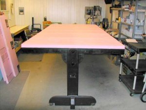
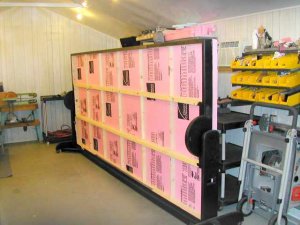
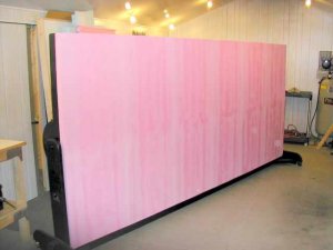
I looked into modular construction techniques and decided it just wasn't for me at this time. So I decided to go with a rotatable tabletop/island verses the room perimeter version I had before. One of my friends helped me with the construction of a new tabletop unit and a couple of pictures are attached. The tabletop size selected is 12' x 5 1/2'. This is the maximum size that could be moved [rolled] through the doorways and fit into a finished basement room. The actual layout construction, for however many years it may take, will be done out in my workshop.

As can be seen in the photos the table-top spins easily on a rolling frame. This allows me full access to all parts of the board, top and bottom, without crawling under or excessive reach-overs. The tabletop locks in at 7 different positions/angles. Although technically a stand-alone tabletop I can see this also being merged as a peninsula into a larger perimeter type layout in the future.

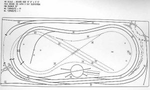
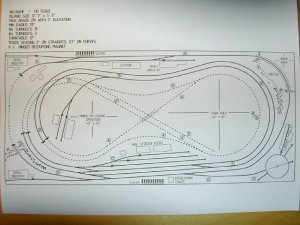
So the canvas is prepared but what to paint? (this is where your input assistance comes in). I have attached in subsequent posts below a version of John Armstrong's freelanced and realitively simple "Springer and Cinncinatus" layout design and additional information.

Thanks in advance to the forum for any comments/concerns and the opportunity to be part of the gang.:)

RailThumper

P.S. I've been a fan of John's work & books for quite some time and I too will certainly miss his extraordinary talents.:(
 

Attachments

  • DSCN1707.JPG
    DSCN1707.JPG
    31.2 KB · Views: 79
  • DSCN1705.JPG
    DSCN1705.JPG
    38.1 KB · Views: 76
  • DSCN1706.JPG
    DSCN1706.JPG
    22.5 KB · Views: 81

Railthumper

New Member
Nov 22, 2005
15
0
1
65
Here is J. Armstrong's "Springer and Cinncinatus" HO layout I was considering. I apologize in advance for the image quality of the photo as I don't have a scanner or export means of converting an AutoCadd (.dwg/.dxf) file to a raster based (.jpg/.bmp)file. The track elevations are noted in the squares.

This S&C plan has been modified from the original size of 9' x 5' to 12' x 5 1/2'. The extra space allowed an increase from an 18" to 20" minimum radius, a full 2.5" between the tracks and longer lines. The point-to-point line [outermost track], which was a sideways U, has been connected on the left side to form a complete loop. This was only done to allow a second DCC train unattended continuous running at the expense of a true point-to-point operation.

Some of what pluses as I see em' are:

Longer radius visible curves
Roughly 2 scale miles of folded dogbone mainline
Grade of between 1 & 3/4 to 2% maximum
A wee bit of "yard" below the turntable (albiet part of the mainline)
Several industry opportunities
"Ridge" and/or Town along elevated midline to breakup the two sides (but me thinks no scenic divider)
Not so large as to be overwhelmed

Some Cons are:

A "Forced" look with some of the hillside grades/retaining walls where they meet the track (particularly on the right side and just above turntable)
Still may wind up with a spagetti-bowl look/operation
"Smaller" industries and town than I would like

My thoughts are the "spagetti bowl" effect has hopefully been reduced by hiding much of the inner track lines along with the staging tracks (all accessible from underneath). Also the tighter 20" curves are mostly hidden from view with most of the visible curves having a more generous 25 to 32" radius. The turntable is 12" and all the turnouts are #6 except for one #4.

Again, any comments or concerns with this design are greatly appriciated.

RailThumper
 

Railthumper

New Member
Nov 22, 2005
15
0
1
65
Well, :(

The layout photo didn't show up very well in the last post so here is take II:

RailThumper
 

Attachments

  • DSCN1836.JPG
    DSCN1836.JPG
    41.7 KB · Views: 79

hminky

Member
Oct 13, 2004
396
0
16
76
Before one decides to put hidden tracks under scenery, do an experiment. Place some switches on a shelf and put a sheet or tarp over that area and restrict your body access to those tracks. Taking care of that area will be a whole lot of fun:curse: . Been there done that:eek: . I would never hide switches on a layout they have a 99.99% chance of never functioning well:cry: . I probably would never hide track of any type on a layout.

Just a thought
Harold
 

Railthumper

New Member
Nov 22, 2005
15
0
1
65
Tough crowd...but that's exactly what I looking for! ;)

I'm not wedded to this particular layout, just the tabletop that I've already built. That's why I posted all this here hoping for just this kind of feedback.

Russ, the dotted lines are hidden track on this plan. As the photos of the tabletop show I haven't done any layouts or cuts on it yet. IF I was to go with this S&C plan, I would cut a large hole through the foam-base to within 1.5" of the hidden tracks for underside access. This would have to be done on both the left and right sides. Mr. Armstrong's original design, which I may have misapplied here, was to have removable "circus tent" center sections for access.

Hminky, Thanks for bringing up your concerns over the hidden turnouts. Not having hidden turnouts in any of my previous layouts I didn't know if they were strictly a big no-no. The one thing I had hoped would be in my favor is the ability to rotate the tabletop to vertical (either way) and be able to sit alongside [in a chair], reach in and work on the turnout...and maybe use a mirror to see better or maybe just mount small mirrors permanently on the underside of the scenery foam-base above the turnouts. In any case, like you say it looks problematic to service troublesome hidden turnouts.

I have had long tunnels in the past with underside access for the occasional problem and found them acceptable.

I'd like to consider going a different direction if anyone has alternate layout plans. I'm not too concerned at this time which industries, etc. that I will install having about 40 to 50 buildings on-hand from the old layouts. From among these I will pick and choose which ones to keep and/or augment.

RT
 

zedob

Member
Dec 26, 2004
757
0
16
62
Chicopee, MA
I like the track plan. I'd definately would kill the hidden storage. It's a good layout to let one or two trains fly around the DB while you are busy with switching chores, or visa versa.

The scenery could easily enough be made removable for access purposes, but the pieces might keep falling off when you tilt the table. Speaking of, do you have some sort of outriggers that can mount to the base once the layout is in the horizontal position? It looks like it may be top heavy.

From my own past experience(s), anything that is mechanical better be accessible. Track alone is not that bad, but turnouts are another thing, unless you have easy access to them. However, with this design, if you need to work on something in the middle of the layout all you have to do is turn it on it's side. Bad thing about that is that trains don't run on walls, so you'd have to flip it back down for each trial run.
 

Russ Bellinis

Active Member
Feb 13, 2003
4,501
0
36
78
Lakewood, Ca.
Visit site
zedob said:
Speaking of, do you have some sort of outriggers that can mount to the base once the layout is in the horizontal position? It looks like it may be top heavy.

You would really need only one outrigger. If you run one brace from the center trestle to wherever it falls on the end with the table flat, you will brace it so it won't move. Make the brace the right length and lock it with a removable pin, then when the table is put in the vertical position, a second hole on the center part can be used to lock it in the vertical position. That way, no matter which way you are working, it won't flip the other way and clobber you. The other thing to think about is are you going to permanently fasten down details and structures, or make them removable? If they are removable, you will need storage off the layout for both trains and structures. If you construct a shelf unit slightly longer than the layout, and leave enough space between the floor and the bottom shelf, you could store your trains and structures on the shelves, and roll the layout in the folded position right up to the shelves with the trestle legs under the shelf unit. That would make compact storage to allow other uses for the room the layout is in.
 

Railthumper

New Member
Nov 22, 2005
15
0
1
65
Thanks guys for the input. Please keep it coming...:)

Russ, I have visited that site several times in the past year and couldn't find much in the larger tabletop layout configuration. I may be wrong but it seemed that the sizing requirement was to be able to fit into a minivan and upsizing the designs just wasn't working for me. On the otherhand the photo gallery and some of the articles have been useful references.

Zedob, you and Hminky have me thinking of scrapping the hidden staging so only flex-track will be hidden. I guess another approach to servicing hidden turnouts, besides removing scenery, would be some sort of "mini-module" approach: a small 14" or so removable plate with the turnout mounted on it. Problem with that idea is maintaining good alignment with the non-removable rails [even with alignment pins] and the fact I couldn't run a test train through the switch when removed from the tabletop.

Russ and Zedob, so far the tabletop has been extremely stable. I know from the pixs that it could certainly look top-heavy. I tested it by placing about 90 lbs. on one edge and it didn't flip over or give. Of course it hasn't been loaded up yet with scenery, etc. I think your idea of outrigger(s) that swing down from the outer edge would be good for safety and rock solid stability once the layout is moved into it's room. For reference, the tabletop pivots are 3/4" steel bolts installed in metal sleeves and the two position pins are 1/2" steel that slide through metal sleeves.

Russ, good concept for a storage shelf system. I think down the road I might implement that idea for storage of the trains. BTW, the plan was to have everything attached securely to the board except, of course, the trains ;) .

One thing that bothers me with this S&C layout is the lack of a "deep" gorge and a nice long curving or straight trestle-type bridge. Any ideas?

RT
 

Russ Bellinis

Active Member
Feb 13, 2003
4,501
0
36
78
Lakewood, Ca.
Visit site
Railthumper said:
One thing that bothers me with this S&C layout is the lack of a "deep" gorge and a nice long curving or straight trestle-type bridge. Any ideas?

RT

You only need the perimeter frame and cross members to keep the layout rigid. If you want to model a gorge and trestle, decide exactly where you want it. Once you know exactly where it will go, if it will come all the way to the edge of the benchwork (this will work better on the side than the end) then you can modify the frame. I don't know if you are familier with hot rods, but hot rodders have a method they have used for years to make more room for heavy duty rear axles in the back of roadsters. They refer to it as a "Z'd" frame. The frame is cut just in front of the axle, a section is welded in that goes up at an angle, and then another section is welded to the angle parallel to the original frame. What you will do is a double "Z". At the spot where you want your gorge, cut a 1 x 4 at the angle you want the sides of your gorge to run and as long as you want the depth of the gorge to be. Use a second 1 x 4 as a gussett. It willl be screwed and glued to the inside of the original frame member and the "Z" section. Repeat the procedure at the other side of the gorge. Your frame should now have two reinforced pieces of wood hanging down on one side (both sides if you want the gorge to go all the way across). Now connect the two "Z" pieces across the bottom with another 1 x4 and a 1 x4 gussett to the inside screwed and glued to reinforce the bottom of the frame. Now you can use a circular saw to cut out the original part of the frame above the gorge. Use a jig saw to cut out the table top at the gorge to the shape you want the gorge to run. I would suggest lining the gorge with window screen from the hardware store, and then use some of Woodland Scenics plaster cloth to make a hard shell inside the screen wire.
 

Railthumper

New Member
Nov 22, 2005
15
0
1
65
Russ,

Thanks for the framing reinforcement suggestion. After thinking bout' it, I believe my biggest concern regarding the gorge is where on the layout to put it for the best visual effect. To my peabrain the S&C plan just doesn't offer much opportunity for such a feature.

I also have concerns over the grade...it works out to just under 2%. John's design fortunately has all the grade changes in full view but my concern is with maintaining speed on the grades. I want to go DCC this time around (with decoder back EMF), use consists, and from time-to-time be able to leave the trains in a continuous-run mode. Is this grade too steep to make this possible??

Also is the quasi-yard on the plan doable? Is there enough there for build-ups/tear-downs?

RT
 

GeorgeHO

Member
May 3, 2005
170
0
16
Baltimore, MD
The problem with the hidden switchs is very easy to fix. If you look at the Hidden area, it only crosses the exposed track in two places which are close together, a double track line, and a siding. If you just build the elevations opposite of what you had intended, the hidden track will now be exposed and cross over top of the other track. Just redraw you layout and subtract the current elevations from 4 - old 4 becomes 0, old 0 becomes 4. Of course this might not result in a good scenic layout compared to what you had intended, but your hidden trackage will be virtually nil, and you wont have to worry about what hidded tracks are occupied, how the switches are thrown, what cars are off the track, etc.

Also, where the hidden track crosses over 3 hidden tracks, just to the upper right you have a 0 and a 4 close together, Is there enough room to have the over/under there?
 

Russ Bellinis

Active Member
Feb 13, 2003
4,501
0
36
78
Lakewood, Ca.
Visit site
Railthumper said:
Russ,

Thanks for the framing reinforcement suggestion. After thinking bout' it, I believe my biggest concern regarding the gorge is where on the layout to put it for the best visual effect. To my peabrain the S&C plan just doesn't offer much opportunity for such a feature.

I also have concerns over the grade...it works out to just under 2%. John's design fortunately has all the grade changes in full view but my concern is with maintaining speed on the grades. I want to go DCC this time around (with decoder back EMF), use consists, and from time-to-time be able to leave the trains in a continuous-run mode. Is this grade too steep to make this possible??

Also is the quasi-yard on the plan doable? Is there enough there for build-ups/tear-downs?

RT

2% is not a bad grade at all. Generally grades don't cause problems until you get to 3 1/2%-4%. If you are running modern diesel, you can always mu extra power to help with the grade. Regarding the quasi yard, one is hidden which won't be much use, the other one looks like three run around tracks. If there is a weakness in this layout, it is that there isn't very much switching interrest available. It also looks like there might be at least two reversing loops. Even if you run dcc you will have isolate the reversing sections and allow some sort of automatic reversing to keep the trains running through the loops.
 

Railthumper

New Member
Nov 22, 2005
15
0
1
65
George, I'll have to think long and hard about reversing the elevations. Just don't know what that would do to the scenery...may have to build a rough mini-model to get the "picture". I think the over-under your asking bout' on the upper right is ok.

Russ, your the jauggernaut round here
thumbsup.gif
. Thanks for putting me at ease on the grades. I had 2% grades in the last layout and the DC trains always had speed/stalling problems. Maybe DCC, decoder BEMF and more careful track laying will be the cure.

Originally posted by Russ Bellinis:

If there is a weakness in this layout, it is that there isn't very much switching interrest available. It also looks like there might be at least two reversing loops. Even if you run dcc you will have isolate the reversing sections and allow some sort of automatic reversing to keep the trains running through the loops.

Russ, it will be appriciated if you (or anyone) could suggest improvements on the yard design.

BTW, I added up the length of track [in CADD] and it comes to just over 190'. Hope this isn't going to wind up looking like a sgetti' bowl or too much track.

RT
 

Russ Bellinis

Active Member
Feb 13, 2003
4,501
0
36
78
Lakewood, Ca.
Visit site
One thing to keep in mind about grades has to do with the quality of your locomotives. Gauge members constantly advise newbys to buy quality locomotives. Athearn, Atlas, Lifelike P1k and P2k, Bachmann Spectrum, Kato, and BLI will all be heavy locomotives with all drive wheels powered, and will have no problem with a 2% grade. A train set locomotive from Lifelike or Model Power or Bachmann will frequently have one truck powered and the other just picking up power. They will be very light weight and just won't pull as well. I haven't figured out how to draw on the computer, but there are quite a few guys here who do. I would expect some of them to chime in pretty soon with ideas.
 

Railthumper

New Member
Nov 22, 2005
15
0
1
65
Russ Bellinis said:
One thing to keep in mind about grades has to do with the quality of your locomotives. Gauge members constantly advise newbys to buy quality locomotives. Athearn, Atlas, Lifelike P1k and P2k, Bachmann Spectrum, Kato, and BLI will all be heavy locomotives with all drive wheels powered, and will have no problem with a 2% grade.

Russ, the Locos are a mix of P2K SW9/1200, P2K E8/9, some Life-Likes and half a dozen assorted brass or zinc cast steamers. Only one of the steamers have had the open armature motor replaced with a quality 5-pole motor/flywheel arrangement.

Russ Bellinis said:
I haven't figured out how to draw on the computer, but there are quite a few guys here who do. I would expect some of them to chime in pretty soon with ideas.

Thanks Russ. I certainly could use their help!

RT
 

Russ Bellinis

Active Member
Feb 13, 2003
4,501
0
36
78
Lakewood, Ca.
Visit site
If you don't get a response to this one before the weekend is over, you might want to bump this up after the weekend is over. Some of those who do layout planning may be busy with family over Thanksgiving and haven't been here lately.
 

Railthumper

New Member
Nov 22, 2005
15
0
1
65
Russ,

I took your suggestion on the yard and came up with this alternate layout design and added more detail to kinda show whats going on. Picture is attached below. The turntable was moved into a corner and a three-legged yard added along with other minor changes. Should we give the yard an in-and-out from both ends at the expense of some length...and is this desirable?

I'm leaning towards the "Hump Yard Purveyance" type mechanical turnout lever controls and maybe using some more of them to operate hinged undertrack decoupling magnets (not exactly prototypical). Possible lever locations are shown alongside interlocking towers on the drawings. Speaking of decouplers, just where is the correct place to put them on yards and spurs anyway?

The hidden sidings have been reduced to just one...easier to keep track of. I can mount the single turnout and a bit of track as a removable-from-underneath module for servicing. Fortunately, I already have spare mini black & white cameras, transmitter/receiver and several IR illuminators for keeping an eye on the hidden staging and turnout.

Down the middle of the board lengthwise will be higher scenery, hills, town, etc. to help visually divide the two sides without actually using a scenic divider. It's kind of hard to tell but the lowest elevation of the areas shown for the town and mining or logging are at least 8" above the perimeter of the board. Also a "gorge" area was added in the upper right corner with a curved trestle bridge.

BTW, you guys will probably think this one is truly bent (sort of like me I'm told)
rolleyes.gif
:
We took the tabletop and tilted it to 90 degrees (straight up/down) to make the equivilant of a projection screen. I then took a data/video projector [from about 25' back], a notebook PC, loaded up the drawing and projected the proposed layout right onto the tabletop!! It allowed me to hold-up buildings for placement ideas and generally visualize the layout without marking it up.

Oh, almost forgot; doing the easements was super-easy using CADD. I think I'll just trace the projected lines when it comes time to put pen-to-the-board
wink.gif
.

RT
 

Attachments

  • Layout Take 2.JPG
    Layout Take 2.JPG
    64.5 KB · Views: 59

Russ Bellinis

Active Member
Feb 13, 2003
4,501
0
36
78
Lakewood, Ca.
Visit site
That should work very well. The original "yard" tracks provide various combinations of run around tracks, so you don't need to have an entrance to the yard tracks from both ends. I think trying to make them double ended would take so much real estate that you couldn't fit many cars on them anyway.