My Milwaukee Road Riverline Division Future Layout

Dec 10, 2007
141
0
16
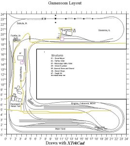
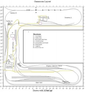
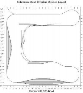
View attachment Stevec-Milwaukee Road Riverline Division Track Plan Finalized.xtcHello,I have decided to change the era and area modeled on my future layout,I renamed the towns and industries and reworked the track plan,eliminating the 8 crossovers that were planned for the layout.The area modeled will be from Ottumwa,Iowa to Savanna,Illinois from 1981-1985,since I am most familiar with this area and have visited this ares plenty of times in thee past.The towns on the layout will be,Ottumwa,Washington,Fairfax,
Linwood,Davenport,Sabula and Savanna.The industries I am modeling are,Cargill,Circle B Lumber,Oscar Meyer,Linwood Stone and Gravel,Mississippi Valley Grain,Fairfax Grain,Linwood scrap yard.The radius and layout size will be the same as before.The scale will still be HO Scale,and MP15AC's and SD40-2's will be used for the motive power along with 85 freight cars and 4 bay window cabooses.I will use 4 MP15 AC's and 4 SD40-2's.I have included the latest track plan revision.All replies are greatly appreciated.Hopefully I will be able to start the layout by the end of the year,now that I have an attorney working on getting my disability for me.I will have more updates later.
 
Dec 10, 2007
141
0
16
Here's a view of the track plan and the changes made to it.
 

Attachments

  • Steve Church Layout Milwaukee Road Riverline Division Finalized Track Plan 2.bmp
    185.9 KB · Views: 121

railohio

Active Member
Dec 29, 2000
999
0
36
If you want feedback we'll need a larger version of the plan, preferably in .jpg format, too.
 
Dec 10, 2007
141
0
16
here is the plan in jpg format let me know what you think of the plan,I still plan on access hatches for the hard to reach areas.
 

Attachments

  • Steve Church Final Track Plan Milwaukee Road Riverline Division.jpg
    Steve Church Final Track Plan Milwaukee Road Riverline Division.jpg
    92.1 KB · Views: 62

railohio

Active Member
Dec 29, 2000
999
0
36
The .jpg is much appreciated. I suppose now that I study it I see a larger and more detailed version probably isn't available. I'll just squint at this one some more.
 
Dec 10, 2007
141
0
16
Here's another view of the track plan,if the plan is not correct for the area modeled from Ottumwa,Iowa to Savanna,Illinois from 1981-1985 please feel free to make changes.I want the track plan to be correct for the area.Thanks in advance.
 

Attachments

  • Steve Church Final Track Plan Milwaukee Road Riverline Division.jpg
    Steve Church Final Track Plan Milwaukee Road Riverline Division.jpg
    83.3 KB · Views: 43

Russ Bellinis

Active Member
Feb 13, 2003
4,501
0
36
78
Lakewood, Ca.
Visit site
The only problem I see is at the main yard. The bench work appears to be 6-7 feet wide and I don't see space for an access panel between all of the tracks. I think you need to have a hole at least 18" x 36". If the 24' x 24' is only the layout size and the room is bigger to allow access behind the main yard, the problem is solved.The other 2 parts of the layout have plenty of open space to allow access panels.
 
Dec 10, 2007
141
0
16
That's the only space I will have,We are hoping the basement will be larger than the 24'x24' layout,hopefully 35'x35'.WE will have to wait and see what size a basement we get,when the wife and I rent a house.
 

Russ Bellinis

Active Member
Feb 13, 2003
4,501
0
36
78
Lakewood, Ca.
Visit site
If you get a big enough basement that you can move that one leg away from the wall, you should be good to go. If not, you will probably need to modify the plan a bit. By the way, what is the yellow line in the plan? If that line wasn't there, you could probably have room to put in the access hatch.
 
Dec 10, 2007
141
0
16
Here is an alternate plan I drew with X Trax Cad and have converted it to a jpge.let me know what you think,feel free to re do changes in the plan if you like. This is the first plan I have drawn with Trax Cad by myself.
 

Attachments

  • Copy of Test Plan.jpg
    Copy of Test Plan.jpg
    59 KB · Views: 19

Russ Bellinis

Active Member
Feb 13, 2003
4,501
0
36
78
Lakewood, Ca.
Visit site
An access hatch can easily have a road through it, I thought it might be some sort of trolley or interurban line. I think that the 2nd track plan might be a bit "yard heavy". The last 5 or 6 tracks in the yard on the left side look to be too short to serve any purpose. The last one doesn't look like there is room to leave even one car without having it foul the track going around it.
 

nolatron

Member
Nov 17, 2004
716
0
16
44
Katy, TX
railroad.sodh.net
I would try to make it an "around the wall" layout, maybe with an island for the the yard.

It'll shrink the depth of the layout and give you a more linear layout (train passes each soon once).
 

Russ Bellinis

Active Member
Feb 13, 2003
4,501
0
36
78
Lakewood, Ca.
Visit site
On further thought about your layout proposal, I think I would have to agree with Nolatron. You can't use an access hatch next to the yard. The only way to work that yard reliably would be to put in a permanent operators pit in between the main yard and the yard marked "engine, caboose, & mow." You would need to use a duck under to get to it. Unless you always have 2 operators, one to run the main yard and one to run the rest of the layout, you will get tired of ducking under the layout constantly to work the yard, then come out to run trains. You would need the same sort of operator's pit to work the left side industries and yard. The only place where an access hatch would be useful would be at the top. The other way to do it would be to make all of the bench work 2 feet wider, put in a single duck under or lift bridge, and then open up the center of the bench to make a "C" shaped operator's pit. Then you would duck inside, and operate the entire railroad from the pit. The only way to comfortably operate that layout as drawn is to put it in a basement or room that is at a minimum 30 feet x 30 feet so that you can walk all the way around the layout.