The more I look at it, the more I am surprised you don't add another section to the layout to the right side. You've got plenty of room there
My Future Milwaukee Road Iowa Division Update
- Thread starter stevechurch2222
- Start date
You are using an out of date browser. It may not display this or other websites correctly.
You should upgrade or use an alternative browser.
You should upgrade or use an alternative browser.
My Future Milwaukee Road Iowa Division Layout Update
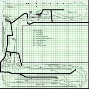
it is due to the fact that I have back problems,arthritis in my back,and a bone that is not fully grown,so I want to avoid a duck under for that simple reason.I feel this plan has a lot of operational potential,and will be a lot of fun to operate.it will take quite a few years to get the layout finished,but that is the fun of this hobby.Nothing can be built in a day,it will take time to get this layout started and finished,but I look forward to it.This is the first layout I have really enjoyed the track plan,and I want this layout to run like the real railroads run,as prototypical as I can.I will have an update in a day or two with the track plan,hopefully the finalized track plan.Structures are being added to the track plan as part of the final track plan.The structures will be switched by the cars that serve the structure.
it is due to the fact that I have back problems,arthritis in my back,and a bone that is not fully grown,so I want to avoid a duck under for that simple reason.I feel this plan has a lot of operational potential,and will be a lot of fun to operate.it will take quite a few years to get the layout finished,but that is the fun of this hobby.Nothing can be built in a day,it will take time to get this layout started and finished,but I look forward to it.This is the first layout I have really enjoyed the track plan,and I want this layout to run like the real railroads run,as prototypical as I can.I will have an update in a day or two with the track plan,hopefully the finalized track plan.Structures are being added to the track plan as part of the final track plan.The structures will be switched by the cars that serve the structure.
Attachments
You don't need a duckunder to expand the plan. You could go from a C shape to a G or inverted G.
Anyway, I'm wondering what the point is of the inner return loop at Council Bluffs. It doesn't look like you can run continuously through it.
Anyway, I'm wondering what the point is of the inner return loop at Council Bluffs. It doesn't look like you can run continuously through it.
Steve, I didn't mean to fully enclose it, but just to add another, say 5x5 (or so) to the right end, into the middle, which would still leave a 5' walkway into the center. this would be nice to add another yard, industry, branch line, town, etc. Heck, maybe even a roundhouse to store un-used locos
I plan on leaving the plan as is,I will post the updated plan when I receive it,should be either sometime today or this weekend.The loop going from Council Bluffs like I said before is the branch line.
I will have the finalized plan,either Saturday or Sunday,and I will post it.I really like the plan and it will provide a lot of operational potential and fun.
My Future Milwaukee Road Iowa Division Layout Update
Here's the latest updated track plan,the finalized plan will be ready this weekend and I will post it.The swing truss drawbridge span needs to be changed from 140' to 364' and the girder bridge placed next to the swing truss drawbridge.Access hatches have been added and the roads and griswold crossing gate signals where they will be placed will be added.The plan is looking really good.
Here's the latest updated track plan,the finalized plan will be ready this weekend and I will post it.The swing truss drawbridge span needs to be changed from 140' to 364' and the girder bridge placed next to the swing truss drawbridge.Access hatches have been added and the roads and griswold crossing gate signals where they will be placed will be added.The plan is looking really good.
Attachments
My Future Milwaukee Road Iowa Division Layout
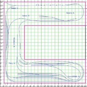
Here is the latest update of the track plan,the finalized plan will be finished tomorrow and I will post it to this thread.The swing truss drawbridge span is 364' and the other spans will be 150' each both of them and the girder bridge will be 50'.
Here is the latest update of the track plan,the finalized plan will be finished tomorrow and I will post it to this thread.The swing truss drawbridge span is 364' and the other spans will be 150' each both of them and the girder bridge will be 50'.
Attachments
Steve
I've opened the track plan you posted at the XtrkCad group with XtrkCad. The good news is that there are only 2 places with red track - a minimum radius violation or similar - and these are not on the main line.
The bad news - and I'm being my blunt, negative self here - is that if you use this plan, you will spend a couple of thousand in construction. Then you will abandon the layout, tear it down, or give up the hobby. I know you are set on the plan, but it's not a feasible plan except for the most dedicated, non-handicapped model railroaders I can think of.
When I was 10, my father and I built a 6ft x 13ft HO layout against the wall (13ft side). We put in a couple of access hatches to build and maintain the track near the wall. Even as a healthy pre-teen, I grew to hate ducking under to get to those access hatches. The back tracks were neglected because nobody wanted to use the access hatch on a regular basis, and the layout became more and more dysfunctional. After about a year it was abandoned (without any scenery), and a year later boxed in when we moved overseas. When we returned to the house 3 years later, the layout went into the dumpster without any regrets.
When my father retired, he built a large donut shape with an extension for a yard. He was in the middle of the wiring when he injured his back and shoulders. Even though I offered to finish the wiring for him, he refused and gave up all but the yard because the ducking under was too painful. After a year or so, he just built structures because the main line didn't function well enough to move trains in and out of the yard. Two years later, he gave up the hobby completely.
I tell these stories because they are true, and because you are headed down the same road. You rightly rejected an around-the-walls plan because of your disability. That same disability is going to make those access holes very painful to use on a regular basis. Similarly, wiring underneath the layout is going to be a challenge for you. I don't know about you, but for me model railroading is an enjoyable hobby. That means the tolerable pain thresholds are lower than for normal life. In real life, I have to deal with unpleasantness as it comes my way. In my hobby, I don't unless I choose to.
Another take-away is that the access holes in the lower part of the plan are 6 ft apart, which means a difficult 3ft reach. Given your disability, what is your real reach across a layout of planned height? How long can you sustain that reach? Do you need to sit often, or most of the time? What is the long term prognosis for your back - is it stable, or will it likely deteriorate further?
There are plenty of model railroaders with disabilities - but their techniques, materials, and layout plan are adapted to not conflict with their disability.
The easiest way to fix your layout is pull it out from the walls to create a back aisle, and shrink the plan as necessary. Other possible directions include switching to N or 3 rail O, or picking a theme that can use 18" radius curves in HO (what I do).
Or change the layout configuration to conform to a height, wiring and under layout installations, and reach that suit you. I would suspect that you would be much happier with an 18" deep shelf against the wall, at a height that suits you. Wiring would be on a shelf beneath the "track shelf" and brought to the front as much as possible. A swing gate would be a lot more usable than the access hatches, and could give you a nice continuous run.
just some thoughts and suggestions - ultimately you decide.
The layout will be built away from the walls,so I will be able to reach the hard to reach areas.I can reach from about 3'-3 1/2'.Thanks for the suggestions.
I would of gone to N Scale,but due to the lack of models I need for the layout,that's why I am still in HO Scale,I model the SD40-2's in the early version and in N Scale they are next to impossible to find,and there are no MP15AC's in N Scale like there is in HO,and no willingness with any of the manufacturers to produce them,and I don't see that changing in N Scale any time soon for the MP15AC or the early version SD40-2's.Lack of any decent bay window cabooses and decals,plus decalling in N Scale is much more difficult than in HO.I have taken my back problems into consideration,and would not build a layout against the walls.Again I thank you for bringing these things up,you all here in this group are very helpful,and I am grateful for this,and the opportunity to be a part of this group.
I would of gone to N Scale,but due to the lack of models I need for the layout,that's why I am still in HO Scale,I model the SD40-2's in the early version and in N Scale they are next to impossible to find,and there are no MP15AC's in N Scale like there is in HO,and no willingness with any of the manufacturers to produce them,and I don't see that changing in N Scale any time soon for the MP15AC or the early version SD40-2's.Lack of any decent bay window cabooses and decals,plus decalling in N Scale is much more difficult than in HO.I have taken my back problems into consideration,and would not build a layout against the walls.Again I thank you for bringing these things up,you all here in this group are very helpful,and I am grateful for this,and the opportunity to be a part of this group.
Sorry, I misunderstood the plan. Forget about what I said about access. With your long comfortable reach and the relatively low layout, you probably don't even need the access holes.
I would make a plan in advance for wiring without having to bend over a lot. Some suggestions:
- use DCC to avoid all the block wiring (you're probably ahead of me here)
- solder many of your track joints to reduce number of feeders and/or dependence on rail joiners to conduct track power long term.
- set up a chair to roll under the layout that puts your head and arms at a reasonable height for wiring work
- consider routing some or all wires on top of the layout and under the track through grooves cut in the roadbed. Fill over top the groove with a piece of styrene or cardstock and ballast normally.
I plan on going to DCC,that's the only way to go these days.Simplifies wiring and you can run a mainline train,and either switch the industries or the yard.I will probably get a chair that I can roll under the layout for wiring.I plan on soldering as many joints as possible for better conductivity.
My Future Milwaukee Road Iowa Division Layout Update
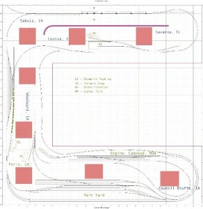
Here is the finalized track plan,I really love how the plan has turned out.Hopefully my disability claim will be approved so I can start construction of the layout this summer or this fall.I don't have a program to convert the file to a jpg or jpeg format.
Here is the finalized track plan,I really love how the plan has turned out.Hopefully my disability claim will be approved so I can start construction of the layout this summer or this fall.I don't have a program to convert the file to a jpg or jpeg format.
Attachments
All that's left to do on the track plan is to add the roads,overpass king pin "A"frame bridge,and the area where the Griswold Crossing signals with "A" frame gate arms will g ther than that the track plan is done and has been finalized.I don't have a program to convert X Trax Cad files to jpeg,jpe,gif formats.Goals of the layout are,smooth operations,trains ran with timetables,switching done with a card system using way bills for loaded and empties,cars in the yard to be classified according to destination,trains ran at a prototypical speed,block signalling following ABS rules.diesel facillities will include engine movements,and caboose hops at the caboose track.I will post the final version of the track plan as soon as it is done and includes what I mentioned before.
ther than that the track plan is done and has been finalized.I don't have a program to convert X Trax Cad files to jpeg,jpe,gif formats.Goals of the layout are,smooth operations,trains ran with timetables,switching done with a card system using way bills for loaded and empties,cars in the yard to be classified according to destination,trains ran at a prototypical speed,block signalling following ABS rules.diesel facillities will include engine movements,and caboose hops at the caboose track.I will post the final version of the track plan as soon as it is done and includes what I mentioned before.My Future Milwaukee Road Iowa Division Layout Update
Here is the finalized version of the track plan,all that is left to do,is to add the roads,where the "A" frame king pin post overpass bridge will go ,and the area where the Griswold Crossing signals with "A" frame gate arms will be installed.i will post the finalized plan with these changes when I receive it.
Here is the finalized version of the track plan,all that is left to do,is to add the roads,where the "A" frame king pin post overpass bridge will go ,and the area where the Griswold Crossing signals with "A" frame gate arms will be installed.i will post the finalized plan with these changes when I receive it.
Attachments
There will be an updated track plan later on today,that will include the changes I mentioned in my last update,plus a few changes in the plan for better and smooth operations.I will post the plan as soon as I receive it.The main goals of the layout are,prototypical operation,easy access,30" radius on the main line,24" on the branch line,switching off the branch line to serve the industries,cars of the correct type will switch their correct industry.Diesel facilities will have diesel shops for repairs on the diesels if necessary,caboose tracks and MOW facilities.DCC operation for the most realistic train control,signalling on the mainline ABS using single head searchlight signals,grade crossing signals using one pair of Griswold Crossing signals with "A" frame gate arms.May use some double headed searchlight signals at the diverging routes,I will have more information later today and post the plan when I get it.
My Future Milwaukee Road Iowa Division Layout Update
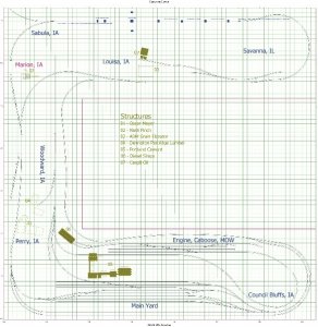
Here is the finalized track plan with changes requested,the roads added,overpass bridge,Griswold gate location,and relocation of some structures.Hopefully the layout can begin construction this summer or fall.I will keep you posted.
Here is the finalized track plan with changes requested,the roads added,overpass bridge,Griswold gate location,and relocation of some structures.Hopefully the layout can begin construction this summer or fall.I will keep you posted.