My first "real" layout

YmeBP

Member
Dec 3, 2006
529
0
16
51
Southern New Jersey
www.skyersfamily.com
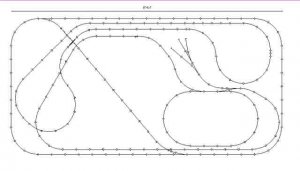
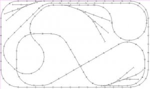
Hi everyone. I'm just back from home depot, i picked up some of that foam board and i'm headed downstairs to begin setting up my first real layout. I used rts 7.0 to draw this up:
attachment.php


It has a couple of issues, i couldn't get the tracks in the north eastern section to line up to make 90degree crossings in the program i have no idea why, but i suspect i will not be able to get the track to line up for 90 degree crossings in real life either hahaha. The other issue is top center the 4th rail down. I couldn't get that to line up either. I used the templates for atlas code 83 tracks but the inner most 2 rings will be power loc.

I have to learn how to use elevations in the program becuase the power loc is to fly above the atlas track and i can't model it correctly in the program. I am also going to need some help wiring my bumpers as i have not a clue as how to correctly use them :eek:ops:.

I've been rading about wiring. the only secitons that re linked are the two inner most rings as i don't know how to wire quite yet. I figrue i'll get this rolling and then play w/ wiring cross segment switches once i get my books in the mail. I boughts some small nails to stick in the little holes in the track to the foam. I have to buy some felt but i'm a little tapped so my layout is going to be pinkish for the xmas season hahaha. :thumb:

Will send pix as time goes on.

Feedback welcome looking to build a bunch o layouts ot learn.
 

Attachments

  • trainlayout.jpg
    trainlayout.jpg
    17 KB · Views: 482

Russ Bellinis

Active Member
Feb 13, 2003
4,501
0
36
78
Lakewood, Ca.
Visit site
The reason that things won't line up is that the program your using, if it is a good one, forces you to use correct radii on curves. If the only way to get the crossover to be 90 degrees is by fudging, most track planning programs won't let you do it. If you "fudge" it in your layout construction to make it fit, you will probably create a place for a lot of derailments.

If you are not very experienced with wiring, don't put in that diagonal track from the top track to the bottom track from upper left corner to lower center. That track created 2 reverse loops, without insulated rail joiners and double pole douple throw switches to reoute the power, you wil create a short circuit.

You have the potential here to run a few trains on a sort of demonstration layout, but there isn't much there to do operation with. If you are looking to build something where you can watch the trains run, this plan will work. I also wonder what the purpose of the small oval in the lower right center is?
 

YmeBP

Member
Dec 3, 2006
529
0
16
51
Southern New Jersey
www.skyersfamily.com
Russ Bellinis said:
The reason that things won't line up is that the program your using, if it is a good one, forces you to use correct radii on curves. If the only way to get the crossover to be 90 degrees is by fudging, most track planning programs won't let you do it. If you "fudge" it in your layout construction to make it fit, you will probably create a place for a lot of derailments.

Thanks for the tip i've notcied that i slipped a 22" radius curve in there some how. I have to adjust that.

If you are not very experienced with wiring, don't put in that diagonal track from the top track to the bottom track from upper left corner to lower center. That track created 2 reverse loops, without insulated rail joiners and double pole douple throw switches to reoute the power, you wil create a short circuit.

I have a couple of plastic insulated rail joiners but i don't think i have a dp dt switch. Do you think if i change it from going backwards to goign in the same direction it would work?

You have the potential here to run a few trains on a sort of demonstration layout, but there isn't much there to do operation with. If you are looking to build something where you can watch the trains run, this plan will work. I also wonder what the purpose of the small oval in the lower right center is?

Yes, i planned on running 3 or 4 trains to get myself oriented to working this sort of stuff out. The loop in the lower right was to get used to laying and operating switches properly. I had a question about the switches, at what angle does the fork come off of it? And why do switches mess up my symmitry? What sized piece do i need to stick on the end of the gimpy leg to make it even?
 

YmeBP

Member
Dec 3, 2006
529
0
16
51
Southern New Jersey
www.skyersfamily.com
ocalicreek said:
Ditto to what Russ said. No offense intended, but what do you mean by "real"? That's a pretty subjective word and can mean many different things to different folks...what does it mean for you?

Galen
By real meaning i didn't follow the instructions that came in the box w/ the trains and i actually had to put some thought into it. Oh and it's on pink foam :D.

None taken :) i'm new my skin is thick let'em fly !!

More humbly stated, i can always use the help. I've been a member for only a week and the people here have saved me money, helped be find what i need, pointed me to very low priced stores, helped me w/ my materieal choices and track choices ... and that's just in the last 6 days!!
 

Russ Bellinis

Active Member
Feb 13, 2003
4,501
0
36
78
Lakewood, Ca.
Visit site
YmeBP said:
I had a question about the switches, at what angle does the fork come off of it? And why do switches mess up my symmitry? What sized piece do i need to stick on the end of the gimpy leg to make it even?

If you turn one of the 2 switches forming the double reverse loop, you will eliminate the reverse loop, but with all of the track you have running already, do you really need another optional route for your trains to take?

Regarding switches, they are measured differently than curves. Curves are measured by their radius, except for Lionel which measures theirs by diameter. The switches are measured by the angle of the frog. If you aren't clear on what the frog is, it is the part of the switch that looks like a frogs back footprint. I think switches also have an easement built into the tangent, so that also makes the curve a bit bigger. If your switches are Atlas Snap Switches, they are probably #4.5. Atlas sells them as a #4, but they are actrually slightly larger than a #4. In Atlas Custom Line you will find not only #4, but #6, & #8 as well.

By the way, I forgot to ask earlier, are all of your loops on the same level? If they are at different levels so that the tracks cross each other on bridges, you won't have a problem. If you are going to have them all at one level, all of those crossings will cause a bunch of headaches. #1 You may have difficulty finding crossings at the right angles for each crossing. #2 If your are running multiple trains, the crossings will play havoc. Every time the tracks cross, you have the potential for a crash.
 

YmeBP

Member
Dec 3, 2006
529
0
16
51
Southern New Jersey
www.skyersfamily.com
Russ Bellinis said:
If you turn one of the 2 switches forming the double reverse loop, you will eliminate the reverse loop, but with all of the track you have running already, do you really need another optional route for your trains to take?

I bought a crap load of switches and i have to some how justify them to the boss/cfo of the house. They serve absolutely no other purpose right now until i can take some quality time w/ a good wiring book and learn how to do reverse segments and power zones/districts etc. Right now based on the current design the outer loop is ~34 linear feet, i've been reading that a good practice is 1 "feeder"(18gauge) per 3ft to 6ft connected to a "bus"(12-14gauge). I don't think my layout is big enough to need a "bus" so i'm going to use 18g stranded copper to a terminal bar w/ star washers and spades w/ conductive gel on the other end.

I'm not really sure how to extend those tiny wires from turnout machines (<== i'm starting to get the hang of the terms!!! :thumb:) to a single point or even if it is a good idea to extend the wires to a single point.

Regarding switches, they are measured differently than curves. Curves are measured by their radius, except for Lionel which measures theirs by diameter. The switches are measured by the angle of the frog. If you aren't clear on what the frog is, it is the part of the switch that looks like a frogs back footprint. I think switches also have an easement built into the tangent, so that also makes the curve a bit bigger. If your switches are Atlas Snap Switches, they are probably #4.5. Atlas sells them as a #4, but they are actrually slightly larger than a #4. In Atlas Custom Line you will find not only #4, but #6, & #8 as well.
Great info :). Frog i understand, tanget i understand too, but what is an easment? I think land in my front yard the township can steal to make the road bigger.

By the way, I forgot to ask earlier, are all of your loops on the same level? If they are at different levels so that the tracks cross each other on bridges, you won't have a problem. If you are going to have them all at one level, all of those crossings will cause a bunch of headaches. #1 You may have difficulty finding crossings at the right angles for each crossing. #2 If your are running multiple trains, the crossings will play havoc. Every time the tracks cross, you have the potential for a crash.

Short answer is yes except for one. I wanted to have a couple 90d crossings, but now that you've mentioned it w/ my children i don't think it such a good idea anymore. I've been reading about presence detection in dcc and got the bright idea that i can use some form of mechanical presense detection and cut power to that section of the track. I like watching the crossings :). I bought a couple of larger lots of track on ebay a few days back so i have 90d for power lock 90d, 60d, 30d, for atlas and thanks to another forum member i have powerloc to atlas converter pieces too.

I'm going to do a little "adjustment" to the drawing and repost. It turns out i didn't buy enough pink sheeting and since i'm doing a layout on the floor i have no way to secure except constuction glue or cement screws/nails. I'll have to noodle on how to make a flexible floor holder that i can replace the pink sheets when needed and or pull them up to put wiring under them.
 

YmeBP

Member
Dec 3, 2006
529
0
16
51
Southern New Jersey
www.skyersfamily.com
So this is what i've got so far. I've built a "table" kinda on the floor. I've put 4 holes going horizontally in the 3 pieces of wood going across. The sections of wood on the left are holding the foam down. I can change them to adjust for 2" foam when i can afford it. On the right i'm building a clasping setup w/ hinges etc to hold down that end of the foam but have the ability to open it up and get under the foam to lay wire. the whole thing is 14' x 8'.

http://www.skyersfamily.com/gallery/v/Trains/Layout1/

I decided to take your advice and scratch the switch for now. I have one more loop of atlas and one loop of power loc. I have enough engines adn track for all the members of the family.

I screwed up my drawing a little so i had to adjust on the layout. I'll post the drawing again tmrw. I have to come up w/ an idea for a slightly more complex route for my 7 year old. the 2 loops are fine for the wife and the little godzilla.

I have a question about joiners: what is the best way to make sure i have a tight contact? Should i squeeze each w/ some pliers b4 i join? I don't think i'm going to solder as i plan to take it apart often :).

I did a small inventory and i think i have as many switches as regular track hahahaha.
 

Jim Krause

Active Member
Apr 7, 2005
1,270
0
36
89
Polson, MT
The rail joiners will be tight enough when they are new to conduct current but it is desirable once you get your layout set up to solder them. Where the real problem with rail joiners comes in is when you start pulling the track apart and re- using them over and over. No, they don't need to be crimped with pliers. I assume you bought code 83 rail joiners for the code 83 track. Is the power lock track code 83 or code 100?
 

YmeBP

Member
Dec 3, 2006
529
0
16
51
Southern New Jersey
www.skyersfamily.com
I think it's all code 100 i checked samplings of the atlas w/ a micrometer and it specs out at .1 inch. I'll have to check the power loc.

The joiners i have say 83/100 on the box. There are tons of joiners on the ends of the track already (bought a bit of it used).
 

YmeBP

Member
Dec 3, 2006
529
0
16
51
Southern New Jersey
www.skyersfamily.com
O.k. i did some thinking, i 've also taken a good look at what i have downstairs and i came up with the attached.

The loop at the lower left is power loc, and it will be elevated above the 2 other atlas loops. I'm trying to figure out where to put the last loop for the last family member :).
 

Attachments

  • trainlayout1.jpg
    trainlayout1.jpg
    16.3 KB · Views: 290

Jim Krause

Active Member
Apr 7, 2005
1,270
0
36
89
Polson, MT
Are the rail joiners flat the full length on the bottom edge? The reason I'm asking is that there are joiners made by a couple of companies, Atlas and Micro Engineering that are transition joiners for going from one size of rail to another. It sounds like you may have some of those. If there is a step on the bottom of the joiner, they are transition type. If they are flat for the full length, they may be for either code 83 or 100. Does anybody else know if there are joiners that can be used for both code 83 and 100?
 

YmeBP

Member
Dec 3, 2006
529
0
16
51
Southern New Jersey
www.skyersfamily.com
I bougth a bunch of atlas ones from hobby hut. They say 100/83 on the package.

I have most of them joined out but now how do i get the balsted track lined up properly!!! It's like trying to hold a greased up snake!!!

I have track pins but where do i start?
 

YmeBP

Member
Dec 3, 2006
529
0
16
51
Southern New Jersey
www.skyersfamily.com
Went back downstairs and took another look. I've got a bunch of existing joiners form the tracks i bought on ebay and there are all different types. From what i understand the code 83 refers to the hieght of the rail being .83"?

The ones i got from hobby hut are kinda curled just a little:

/-\ /-\
| |
--------

terrible ascii art but kinda like that :).

Jim Krause said:
Are the rail joiners flat the full length on the bottom edge? The reason I'm asking is that there are joiners made by a couple of companies, Atlas and Micro Engineering that are transition joiners for going from one size of rail to another. It sounds like you may have some of those. If there is a step on the bottom of the joiner, they are transition type. If they are flat for the full length, they may be for either code 83 or 100. Does anybody else know if there are joiners that can be used for both code 83 and 100?
 

ocalicreek

Member
May 4, 2005
824
0
16
48
Puyallup, WA
groups.yahoo.com
Be careful with used track...if you don't have one already, get an NMRA clearance gauge to check the rails, turnout flanges, points, etc. to make sure they are in gauge. Especially on a layout with a large area, derailments can be pretty annoying after a while. Bulletproof track = many happy hours of running trains!

Galen
 

ocalicreek

Member
May 4, 2005
824
0
16
48
Puyallup, WA
groups.yahoo.com
Oh, and I remember hearing a tip from one of the Kalmbach videos made back in the early 80s. Take a short piece of rail and file down one end along the base, narrowing it a bit, and along the web, ever so slightly. Then clamp this in either a pin vise or drill a hole into a short length of dowel and tap it in with a hammer, securing it with CA or epoxy, making sure the tapered end is exposed.

Now when you tighten a rail joiner with pliers (ever so gently) and squeeze it too far (oops!) you can adjust it by wiggling it open using your joiner-speader tool!

Galen
 

Jim Krause

Active Member
Apr 7, 2005
1,270
0
36
89
Polson, MT
Are you speaking of the three foot long sections of flex track? If so, you need roadbed under the track. It's made either of cork or foam plastic. The roadbed can be glued down to your bench. Split the roadbed lengthwise down the center. It comes partially cut through. Draw a centerline on your bench where you want the track to go. Glue down one half of the roadbed, indexing the center of the piece to your line. Hold it in place with pins or small nails until the glue sets. Add the other half of the piece of roadbed . Glue it in place and hold with pins or small nails as you did with the other half.
To get constant radius curves, make a protractor from a piece of string, a pencil and a nail or tack. measure the length of the radius that you want and tie the pencil on one end of the string. Put the nail or tack at the center of your radius and mark the radius on the bench. We're going hi tech here. Back about 5000 years ago, that is.
After you get the roadbed down, center the track on the center of the roadbed and either glue or nail the track in place. You will find small holes in the ties about every 6 inches. Atlas sells track nails for this purpose. Don't over drive the nails or you will break the ties (Been there, done that)
 

YmeBP

Member
Dec 3, 2006
529
0
16
51
Southern New Jersey
www.skyersfamily.com
Great info, i just layed the track on the foam, bad move i can't pin the track to the foam :). I'll be heading out to home depot or lowes to see what i can come up w/ roadbed wise.

There is this stuff i've been reading about called hemasote, or cork. I've also read about vynil. I'm going to see what is cheapest.

\
Jim Krause said:
Are you speaking of the three foot long sections of flex track? If so, you need roadbed under the track. It's made either of cork or foam plastic. The roadbed can be glued down to your bench. Split the roadbed lengthwise down the center. It comes partially cut through. Draw a centerline on your bench where you want the track to go. Glue down one half of the roadbed, indexing the center of the piece to your line. Hold it in place with pins or small nails until the glue sets. Add the other half of the piece of roadbed . Glue it in place and hold with pins or small nails as you did with the other half.
To get constant radius curves, make a protractor from a piece of string, a pencil and a nail or tack. measure the length of the radius that you want and tie the pencil on one end of the string. Put the nail or tack at the center of your radius and mark the radius on the bench. We're going hi tech here. Back about 5000 years ago, that is.
After you get the roadbed down, center the track on the center of the roadbed and either glue or nail the track in place. You will find small holes in the ties about every 6 inches. Atlas sells track nails for this purpose. Don't over drive the nails or you will break the ties (Been there, done that)