Model Power Signals

Big Don

New Member
Feb 13, 2003
9
0
1
71
Oakville, Ontario
Visit site
Last week I a bought a pair of crossing signals made by Model Power and there were no instructions in the box.

I have two questions:

(1) What power source is required to power the signals?

(2) Is there a detector I can buy/make to trigger these signal lights automatically rather than using the switch that comes with
them?

Thanks
 

shamus

Registered Member
Dec 17, 2000
3,489
0
36
87
UK
Hi Big Don and welcome to the gauge.

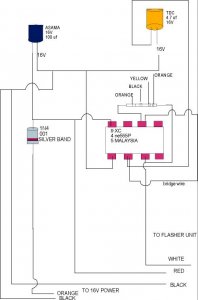
Are these crossbucks? if so, then the drawing below will make the lights flash on and off.


Shamus
 

Attachments

  • flashunit.jpg
    flashunit.jpg
    34.4 KB · Views: 379

Big Don

New Member
Feb 13, 2003
9
0
1
71
Oakville, Ontario
Visit site
Shamus:

Thanks for welcoming me to this site --- I am finding it extremely useful so far.

Are you sure the circuit you attached isn't for a WMD? :D

Now I REALLY wish I had paid attention in that Electric Circuits course I took in university (and barely passed!).

OK --- here are my comments and questions:

- I believe we're talking 16 volts DC ---- correct?
- If memory serves me correctly, what you have marked ASAMA and TDC are capacitors --- correct? What do ASAMA and TDC mean??
- I have absolutely NO idea what you have marked as 9XC/4ne555P/5 Malaysia is!

Why do I have this nagging feeling that I'm having my leg pulled ;)

Regards

Don
 

shamus

Registered Member
Dec 17, 2000
3,489
0
36
87
UK
Hi Don,
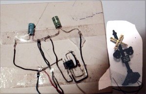
I am not an electronics expert myself, all I know is the drawing works for a flashing set of lights. I myself use it for my crossbucks.

Here it is.

Shamus
 

Attachments

  • f.jpg
    f.jpg
    62.6 KB · Views: 321

Big Don

New Member
Feb 13, 2003
9
0
1
71
Oakville, Ontario
Visit site
Paul:

You were right --- I picked up a 555 Timer IC at the local Radio Shack yesterday.

If you've used these before, perhaps you can answer one question for me.

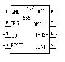
On the back of the package, there is a circuit diagram showing the 'guts' of the timer and indicating what each of the 8 contacts is for: ie

1 = Ground
2 = Trigger
3 = Output
4 = Reset
5 = Control Voltage
6 = Threshold
7 = Discarge
8 = +Vcc

However, there is nothing to indicate which contact is which. Do you or Shamus happen to know if there is a way of determining which is which by using a multimeter??

Thanks

Big Don
 

Freelancer

Member
Oct 24, 2002
309
0
16
Utah
www.yardlimit.com
If you are like me, and all of this electronic talk is going over your head you can try this web site. http://www.berkshirejunction.com/
I got a flashing crossbuck set. It came with an infra red detection system, so that when the train crosses the beam it signals the flashers. I am very impressed with it. There are also quite a few different electronic gadgets similar to it. Good luck.

Freelancer
 

Pitchwife

Dreamer
Apr 23, 2001
1,728
0
36
71
The middle of nowhere Oregon
Visit site
One thing I might add about the capacitors is in referance to the voltage rating. You can always use a voltage rating higher than what your circuit is using. In a circuit that is running 12 volts, a capacitor rated at 100 volts will work as fine as one rated at 35 volts. If you use one that is rated below the working voltage be prepared for some fireworks. :D :D
Also, be sure to observe the polarity of eletrolytics.
 

Paul Davis

New Member
I'd make sure your capacitors are rated at least twice the voltage you expect them to handle. Manufaturers tend to be a little over optomistic when they state the values.

As for the electrolytics, if you do stick them in backwards and they explode you get a big ball of stringy fluff stuff which I'm sure would be good for modeling something.