Mechanical Interlocking - Model

60103

Pooh Bah
Mar 25, 2002
4,754
0
36
Brampton, Ontario, Canada
Visit site
A friend of mine, the late Henry Umpelby, was a mechanical enthusiast and built working interlocking to run his layout. He built the first one, for his station and engine shed, from Lego parts (I never really knew how it worked).
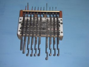
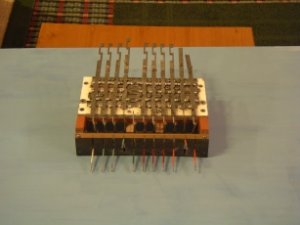
The next one was made from mild steel (for the working bits) and a bit of plastic cove moulding for the top panel. I think the vertical rods operated electrical switches.
The levers actually worked, and you had to pull them off in the proper order to operate the trains. You would set the route, pull off the signals and then run the train. If it didn't run, you had forgotten to pull something.
I think the plant operated two double junctions.
I was given this part of the equipment when Henry died. The layout had already been dismantled. Part of the plant seems to be missing, but doesn't affect operation.
 

Attachments

  • IMGP0399.jpg
    IMGP0399.jpg
    52.3 KB · Views: 116

rcline

Member
Jul 26, 2004
281
0
16
68
Byers, Tx. 76357
www.geocities.com
David - those are some nice photos, what Henry built was called a pull block. Having been around a lot of German machinery for some 30 years now I have seen a lot of them. The Germans used those for just about every type of macanic
 

rcline

Member
Jul 26, 2004
281
0
16
68
Byers, Tx. 76357
www.geocities.com
oops! wrong key -- anyway, the Germans used those for just about every type of mechanical manufacturing equipment that they made. In the late 30's they started using
mechanical relays with a big coils to make and brake electrical contacts. That was also about the time that they started switching over to electric motors and started phasing out the old pull blocks. There is a plastics manufacturing plant in San Antonio,Tx. that has modified an old machine to use for blow molding and it still ran by pulling blocks.
If you can, try to get the rest of stuff that Heney made. It will be well worth it.
 

60103

Pooh Bah
Mar 25, 2002
4,754
0
36
Brampton, Ontario, Canada
Visit site
Most of Henry's layout was dismantled when his daughter and family moved and he only had a small bit of stuff in the nursing home.
He had a lot of ingenious devices in his layout, and posted diagrams (electrical, usually) around showing how they worked.
 

60103

Pooh Bah
Mar 25, 2002
4,754
0
36
Brampton, Ontario, Canada
Visit site
Val:
the vertical bits are connected to a lever at the top end and the stuff to be operated at the bottom end (signals, points, detonators).
The horizontal bits slide back and forth preventing or permitting the levers from moving.
Quick example: if lever 1 is a signal at the points end of a switch and lever 2 is the switch, lever 2 can move freely from straight to curved and back iff lever 1 is at danger. When lever 1 is pulled off (signal to green), the sideways piece is forced over into an indent in lever 2 forcing it to stay in position. When the train has passed, the signal is put back to danger and lever 2 can be moved again.
I have a diagram that I'll try to post this weekend.