Loops

Bob Collins

Active Member
Feb 1, 2001
928
0
36
88
Council Bluffs, IA
Visit site
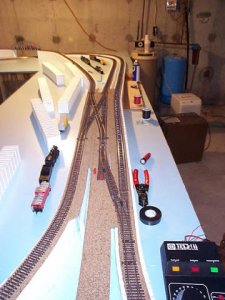
As I hope you can tell from the picture and my few words I am totally confused about wiring this loop and another one on the opposite side of my layout that is of about the same configuration.

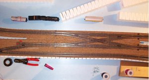
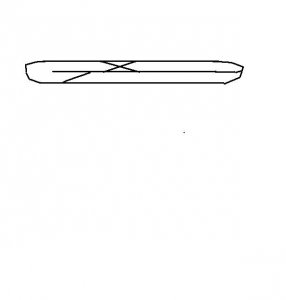
My problem in part is just identifying the loop itself. As you look at this picture the actual loop is at the lower part of the picture. The far right track and the middle one which parallels it feed into the left track which comes around to complete the loop. You can come toward the area where all the turnouts are on any of the tracks, but you cannot cross over going through the turnouts.

What I can't seem to figure out is where the loop actually is within all this.

I do have insulators in the 19 degree crossover. I guess I've come to the point where I am ready to tear it up and start over if necessary to get it right.

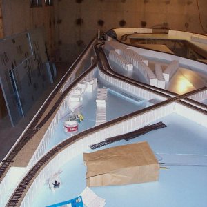
The other loop I have I will need to take a couple of pictures of to put on here as it is slightly different.

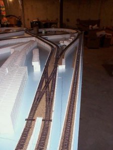
Would also be interesting in hearing from you about which camera angle gives you the best feel for the situation, overhead or oblique?

Bob
 

Bob Collins

Active Member
Feb 1, 2001
928
0
36
88
Council Bluffs, IA
Visit site
And a view from the other end. I ought to say in orienting you that on the last message as you look toward the loop at the far end of the layout the track to the far left up close becomes the outside straight track on the far right. It is a dead end that I haven't decided yet what I'm going to do with it. I have a 90' turntable I could put in at the end of it and there are lots of possibilities. What happens to creat the loop is that I have run a track from the outside loop to the inside track, again you have the same situation as on the other side of the layout where you can basically run around that through the series of turnouts and the crossover, but you cannot come back down the track that leads from the outer loop to the inner one. I'm sure it is just a matter of putting in the DPDT switches, but I'm having difficulty visualizing where they go.

Suggestions and mild criticism are accepted:D

Bob
 

Attachments

  • dcp04735.jpg
    dcp04735.jpg
    58.9 KB · Views: 112

Woodie

Active Member
Mar 23, 2001
2,093
0
36
Northern Rivers NSW Australia
Bob,

I'ts a bit hard to tell from the pics exactly what the layout is. In a simplified form, I have attached a pic of what I think the simplified version is. Is this pretty close? If it is, you can "right click" then "save as" and use MS-Paint to point out where you think (or already have) power and insulators should go. I can see your problem of shorting when you switch the turnouts to "crossover" mode. hmmmmmm. I'll have a think. I assume also, you are using electro-frog turnouts?
 

Attachments

  • billplan.jpg
    billplan.jpg
    12.7 KB · Views: 102

Woodie

Active Member
Mar 23, 2001
2,093
0
36
Northern Rivers NSW Australia
An Attempt at wiring

Bob,

Should I have assumed right, in the simplified diagram, I have had an attempt at a wiring diagram. Shamus is the expert, so, Shamus, what do you reckon?
 

Attachments

  • billwiring.jpg
    billwiring.jpg
    57.8 KB · Views: 102

shamus

Registered Member
Dec 17, 2000
3,489
0
36
87
UK
Drawing please.

Hi Bob,
Please if you can,- do a drawing and post it for me, as it is, - I cannot tell.
Just do a pencil drawing of the plan, photo it and post it.

shamus


Bob Collins

Active Member
Feb 1, 2001
928
0
36
88
Council Bluffs, IA
Visit site
Yeah :) :)

With all of your input and a discussion with one of the "veteran" model railroaders in the new club we are forming here, I have figured it out and am in the process of wiring it correctly:rolleyes: I hope.

My sincere thanks to all of you willing to put up with my ignorance about wiring and other things. I think once I am past this hurdle I am really on my way to getting the layout to look like a railroad. Once I have the yards in place I'm ready to begin the detail work of scenery and right of way work.

Cheers

Bob