

I have a problem, the same as you pointed out, the deck overshoots the bottom of the hull by a 1/4" and I believe this has to do with the laser cut frame? I noticed you showed this in a photo, what I am concerned about is how will this look with hull right side up. I am almost convinced to build as a waterline, then the problem is mute. The upper/lower frame are not glued at this time and I still have that option. I guess one would need to build the frame that comes in the kit to see if in fact that is the problem with the fit of the deck. Did think about trimming off a 1/4" from front of deck, that would not work and create another set of problemswall1. Think I will go waterline on this one.
Ijn yubari 1/200
- Thread starter jkrenzer
- Start date
You are using an out of date browser. It may not display this or other websites correctly.
You should upgrade or use an alternative browser.
You should upgrade or use an alternative browser.
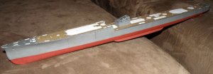
My gap was not so large but it actually is not noticeable right side up. The hull sides act like a curtain and it is not visible when viewed from a normal vantage point. So little of the stern is in the water on these vessels. I would take additional pics but mu wife lost our cable and I can't connect the computer right now.
Looking at it some more. I am thinking the frames may be alright only the stern plate may not be properly shaped to acurately wrap around the deck. I did not have a problem with the framing as much as when keeping the upper hull side lined up with the deck edge when glueing created the gap. Better to leave the gap than to try to snip a shape that is not there.
Jay, after going back and looking at as you pointed out, I believe my friend you are right and it is not the frame but the printed hull sides that create this little delima. I think I am going to go a waterline on this one, heck might try something new for me and put into a sea base. Thanks for you insight. I don't remember if I told you or not, I got a copy of the Titanic and I am just floored by this kit, right now I just look at the pages, pull up your thread and keep saying to myself, it can be built. I did read your instructions to use balsa to laminate too, and when the time comes, that I will do. Rick:thumb:
Thanks for you insight. I don't remember if I told you or not, I got a copy of the Titanic and I am just floored by this kit, right now I just look at the pages, pull up your thread and keep saying to myself, it can be built. I did read your instructions to use balsa to laminate too, and when the time comes, that I will do. Rick:thumb:Well it's spring both Yubari and Titanic will have to wait. Remodeling another room in the house and outdoor activites will cease model production for a while. I'll get back to both later in the summer. Rick I think you'll finish before me. Let us all know if there are any wories in the upper works.
Well, I must admit, I too have set aside waiting to watch you work your magic before I build, however I am building a IJN vessel, the Tone as a waterline. Finishing the frame work now. Your friend, RickWell it's spring both Yubari and Titanic will have to wait. Remodeling another room in the house and outdoor activites will cease model production for a while. I'll get back to both later in the summer. Rick I think you'll finish before me. Let us all know if there are any wories in the upper works.

Well I am back and decided to work more on Yubari, Titanic is still not finished but I want to do this first. It has been a long stretch without modeling but here goes.
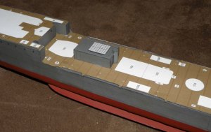
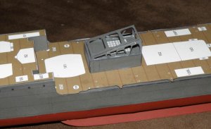
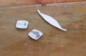
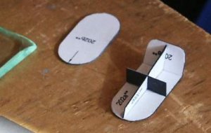
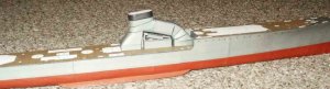
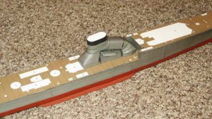
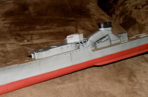
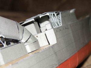
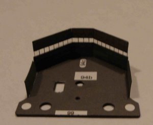
The deck is crowned (curved for drainage) but the superstructure does not account for this. For the structure under the funnel I just eyeballed a conical cut and it seemed to fit pretty good.
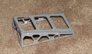
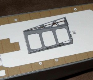
I also made the funnel support cradle. This part I painted the backside before cutting with model master acrylic grey. It actually stiffens the paper some and makes cutting the inner portions out easier.
This weekend I am going to try to tackle the funnel, an odd shaped monster to be built from 2 places and united into one. It contains no less than 11 separate oddly shaped conical pieces all sinergized (not sure that's a word) into one piece. Could be the trickiest thing I have ever seen. Fingers are crossed.
The deck is crowned (curved for drainage) but the superstructure does not account for this. For the structure under the funnel I just eyeballed a conical cut and it seemed to fit pretty good.
I also made the funnel support cradle. This part I painted the backside before cutting with model master acrylic grey. It actually stiffens the paper some and makes cutting the inner portions out easier.
This weekend I am going to try to tackle the funnel, an odd shaped monster to be built from 2 places and united into one. It contains no less than 11 separate oddly shaped conical pieces all sinergized (not sure that's a word) into one piece. Could be the trickiest thing I have ever seen. Fingers are crossed.
Attachments
Glad to see you back @ it. Will follow closely, still have mine, have not progressed any further, waiting to see how your's turns out and other projects: Super Model Bismarck right now.
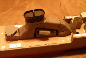
Funnel Construction:
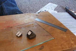
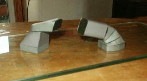
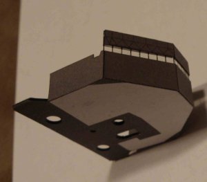
Today I started the funnel. The unit consists of 13 major components and I got 11 done. The seems are visible but I think they are not too bad. IJN raked funnels make English funnels look like child's play.
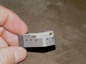
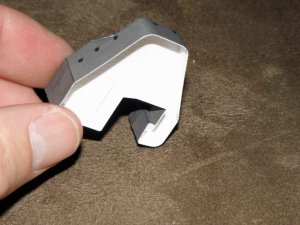
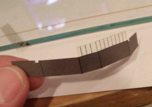
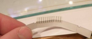
Anyway. I started at both bases, each simple construction. The difficultly begins at the second level and I show a typical piece. It goes together OK and I cut out the center "keel" from the instruction sheet since no former exists. Each section went together reasonably well. My biggest complaint is the color match from one sheet to the next leaves a lot to be desired.
The rectangular piece the stretches between the forward curved uptake and the main section is the worst individual piece which is a shame as it should be the easiest to design.
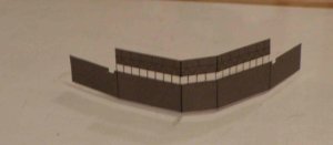
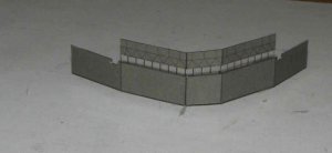
The assembly fits very well and I built up both forward and aft separately to unite them at the end.
You can see the sections but I like it enough that once the various pipes and such are added I think will be difficult to see anyway.
Today I started the funnel. The unit consists of 13 major components and I got 11 done. The seems are visible but I think they are not too bad. IJN raked funnels make English funnels look like child's play.
Anyway. I started at both bases, each simple construction. The difficultly begins at the second level and I show a typical piece. It goes together OK and I cut out the center "keel" from the instruction sheet since no former exists. Each section went together reasonably well. My biggest complaint is the color match from one sheet to the next leaves a lot to be desired.
The rectangular piece the stretches between the forward curved uptake and the main section is the worst individual piece which is a shame as it should be the easiest to design.
The assembly fits very well and I built up both forward and aft separately to unite them at the end.
You can see the sections but I like it enough that once the various pipes and such are added I think will be difficult to see anyway.
Attachments
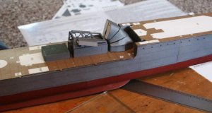
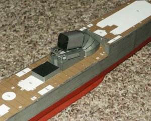
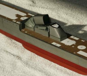
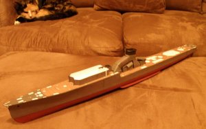
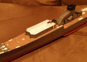
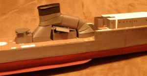
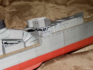
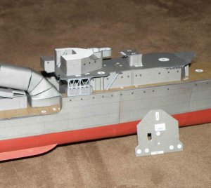
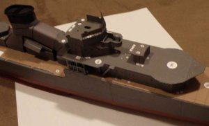
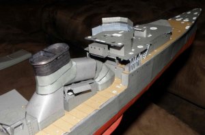
I have started the upper works. The funnel top is installed, I will add the grating much later to prevent handling damage. The vent and search light platform behind the funnel is not glued in place, I will finish it later as well. The forward superstructure is glued to the deck. It will require a few days to finish and I hope to have it done by the weekend.
No problems so far. I am a little dissatisfied with the funnel, I should have filled and sanded it, just I never would have been able to color match with paint.
Overall I hope the funnel gets cluttered enough to disguise the mismatches.
Notice in the upper left of photo 1, monster number 1, the great rigging destroyer all pretending not to notice her next victim.
Attachments
Looking good, the funnel turned out great. I got a little nervous when I saw the furry friend in the back ground, they seem to pounce when you are not looking.
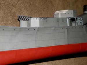
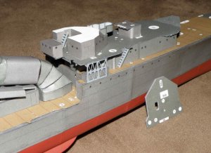
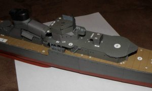
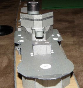
I have started the main superstructure and am up to the second level. I like the way she is fitting out so far. The lower bridge supports were cut out without the X bars, I cut a thin strip of paper and glued them to the back side of the frames. The angle frames have all been added.
The second level of the bridge superstructure is comprised of 2 assemblies, the larger is being built now. I added the center level pattern first then wrapped the skin around it. It has some visible upper works. The lower pattern I glued to the deck and the top is glued lastly to the second level. The upper most pattern I used 1/32 balsa lamination, the other two I used the remaining card stock from the laser cut hull frames.
Next I will finish the second level and move onto the primary bridge. The model is designed with a fully open bridge but ever photo I have ever seen she has a white canvas canopy over the bridge, I will attempt this.
Attachments
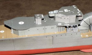
I have finished the second level under the bridge, for the stairs I used model rail road N scale, 1/160, to save time. Difficult to spot is a 1/200 metal photo etch ladder inside between 1st and 2nd levels.
The inner surface of the platform is painted grey as no grey is provided for the kit. The floor for the bridge is cut out and set in place. I still need to add the holes for the mast poles. I laminated it with 2 sheets of black bond to give it more support.
Typically I laminate the horizontal surfaces more than required to keep them from getting wavy, I just adjust the vertical walls a touch to compensate. I just hate wavy decks.
I think I will leave the printed windows in the bridge much to my displeasure, there is just not enough spacing between the to cut them out. To make clear windows I would have to remove them completely and then reinstall. I have not yet decided.
Attachments
E
ekuth
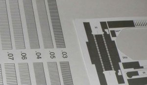
Well I decided to model clear windows after all and am glad I did. Last night I went to bed and the light went off so to speak.
At work I created an ACAD pattern and printed it out on clear vellum. I then completely removed the paper window strip and glued the vellum in 3 pieces on the back side of the folder bridge. I used 3 separate parts to allow it to fold without binding. Then I added to upper lip, using the strip of windows I removed earlier to set the height. After I then added the backside upper strip, again in 3 pieces to allow folding without binding. I painted the lower area and glued the assembly onto the bridge deck. At this time the unit is placed on the ship for pics and it is onto watching some baseball.
At work I created an ACAD pattern and printed it out on clear vellum. I then completely removed the paper window strip and glued the vellum in 3 pieces on the back side of the folder bridge. I used 3 separate parts to allow it to fold without binding. Then I added to upper lip, using the strip of windows I removed earlier to set the height. After I then added the backside upper strip, again in 3 pieces to allow folding without binding. I painted the lower area and glued the assembly onto the bridge deck. At this time the unit is placed on the ship for pics and it is onto watching some baseball.
Attachments
R