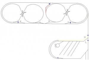
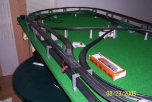
Here is my HO track plan for comment and/or discussion. Each figure 8 is on its own 4x8 table as is the switch yard. It has one oval suspended directly on top of the other. The upper oval extends down to the switch yard only as far as the yelow line. There are two pair of turnouts on each fig8 (for a total of 4 pair)that connect the fig8 to the lower and upper oval. This way a train can travel from the lower oval up one fig8 to the upper oval and then down the other fig8 back to the lower level without having to go backwards or change direction. I have a photo of what I already built to help explain.
The red line is a proposed turnaround that connects to the lower oval(so that I can run trains in either direction without removing them from the track) . The small blue lines are where I plan to insulate track to prevent short circuits. The switch yard is insulated on both upper and lower track. The yellow line is a graduated trestle to connect the upper oval to the switch yard. The turnouts are labled U for connecting to upper oval and L for connecting to lower oval
The red line is a proposed turnaround that connects to the lower oval(so that I can run trains in either direction without removing them from the track) . The small blue lines are where I plan to insulate track to prevent short circuits. The switch yard is insulated on both upper and lower track. The yellow line is a graduated trestle to connect the upper oval to the switch yard. The turnouts are labled U for connecting to upper oval and L for connecting to lower oval