Has to be a Helix

Gary Pfeil

Active Member
May 7, 2001
2,510
0
36
Boonton NJ
Visit site
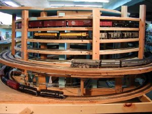
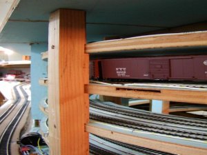
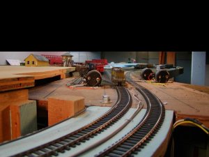
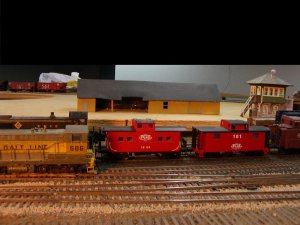
Marty, All the math seems to be in order, until I post helix photos tonight, check the thread "Benchwork 101" in general talk. Two photos in my post there are relevant to your question about supporting the upper level. Photo 3 shows the 2x4 studs which are toenailed into a 2x4 fastened to the concrete floor. You have to take my word for that last part as you can't see the floor for all the crap stored under there. Is there anyone in the area who would like a couple 8' flourescent fixtures? Anyway, it kind of looks like the studs support the l girder, but they are actually about a foot and a half inside the girder. They are attached to joists which span the girders however, for lateral strength. In this photo you can also see the lowest level which is staging for the NYC, which is modeled on the main lower level, just above. You can see a portion of the unpainted backdrop for that level and a bend in that backdrop, the helix is behind that. You can see a steel u channel which is part of the upper level, at the top of the helix. In photo 5, you see the header across the 2x4 studs, with one section of plywood removed to show how I used the u channel inserted in routed out 2x4 pieces flush with the header to support the top deck. Lighting for the main level will be installed beneath the top deck and a valance added. In this photo you can see the fabric covered plywood I used for the backdrop, attached to the same studs supporting the top. And a portion of the main level covered with kit boxes and other misc. debris. All of which will be cleaned off in the next day or two, I swear.
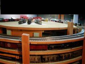
My helix is on a five foot wide peninsula where the main level is divided somewhat down the center by the wall supporting the top. The top is open across so is viewable from both sides. It contains the main yard and engine facilities for the John Galt Line. Well, the yard so far, engine facilities to come where that missing section goes.
If your helix will be at the end of a stretch of benchwork along a wall, then yes, I would cantilever the top level from the wall.

Gary
 

Gary Pfeil

Active Member
May 7, 2001
2,510
0
36
Boonton NJ
Visit site
Marty, We were on at the same time, you have already seen Benchwork 101! For two levels on a wall, I wouldn't use the u channel. Charlie posted shots of brackets used on walls. I have one section of two level benchwork along a wall, i use this type bracket. Terminology is escaping me, bear with me. The piece of wood which runs from the vertical stud to the horizontal joist is essential to the load bearing qualities of the bracket. Yet in order not to intrude too much on the lower level, we want to bring it up on the stud as high as possible. I use (or will use) gussets on both sides of the stud, decided to keep the depth of the upper level 18", and bring out the lower level a couple inches from the studs. I will install a backdrop for the lower level against the studs, bending it to follow the gussets near the top. Although little of this is done yet, I will include a shot of the brackets later tonight.

Gary
 

Gary Pfeil

Active Member
May 7, 2001
2,510
0
36
Boonton NJ
Visit site
Alright Marty, here we go. This is an overall view of the end of the peninsula. You can see just how close the clearance on the helix is. The top level is pretty much out of view here, another shot will show it better. The main or bottom level main is the one with the 20th Century on it. The GP7's are on the staging tracks for the bottom level.
 

Attachments

  • p1010075.jpg
    p1010075.jpg
    95.5 KB · Views: 136

Pitchwife

Dreamer
Apr 23, 2001
1,728
0
36
71
The middle of nowhere Oregon
Visit site
Hey Gary, that's a great shot of your helix. That's the kind of photo that I've been looking for. Thanks for all of your input.
I did some redesigning and changed it so that I will be able to use 2 1/2 revolutions which (if my math is correct) will give me a 2 degree grade and a clearance of 4 1/2 " between levels. A scale model that I made of it seems to back that up. I think that I'll be useing 3/8" plywood for the base and trying a tongue and groove type joint between the sections will give me extra support while still leaving me 4 1/8" clearance. If I mount the track directly on the plywood there shouldn't be a clearance problem for most anything I end up running. I still plan to steal an idea from Trainstyles (www.trainstyles.com) for supports between the layers (see the photo that I copied from their site). I plan to use flex track and soldered joiners all the way through, and I will definately try out your suggestion of laying a section out to make sure that there is enough clearance.
Looks aren't really important for this as it will be hidden so that gives me some extra flexability in the design.
 

Gary Pfeil

Active Member
May 7, 2001
2,510
0
36
Boonton NJ
Visit site
OK, This shot shows the area which will be the turntable and roundhouse which is over the center of the helix. The tracks on the helix dropping down from the top were originally going to be hidden, I'm not sure now, they may be visable till the left side of the picture. I'd gladly here any opinions.The tops of the posts will be sawed off, a retaining wall could be built between levels. What do you all think?
 

Attachments

  • p1010076.jpg
    p1010076.jpg
    82.2 KB · Views: 126

Pitchwife

Dreamer
Apr 23, 2001
1,728
0
36
71
The middle of nowhere Oregon
Visit site
I think that you would be happiest if at least two of the sides were landscaped and at least one was side open for access. Mine is going in a corner so that one side will be landscaped and the other one will have a door. My rationalization is that you don't see anything like a helix in the real world.
 

marty w.

Member
Jun 11, 2002
546
0
16
Bloomington, IN
Visit site
Thanks Gary.

Looks great. Very good construction. I do not think that will every fall apart. That is exactly what I want to do. The 2x2's look like they would give alot of support and rigidity to the helix.

Thanks again. Now it's time to start on the track plan.

Marty
 

Gary Pfeil

Active Member
May 7, 2001
2,510
0
36
Boonton NJ
Visit site
Hi Pitchwife, Reading back I see you said you were planning a 9" seperation (in HO) If both are to be visable, that is not enough. It is only my opinion, but I'd say 14" seperation is minimum, but depends on your height, the heights of the levels and the depth of the scenes. Anyway, the folllowing shot shows my awful carpentry skills. The photo you posted with the threaded rod shows a very good alternative, one which I couldn't use due to a change of plans after cutting the pieces for the helix. I wound up not having room for the rods, and came up with the 2x2's slotted as shown to seperate the levels. they came in handy to support, via angle brackets, the main for the bottom level.
 

Attachments

  • p1010077.jpg
    p1010077.jpg
    75.8 KB · Views: 121

marty w.

Member
Jun 11, 2002
546
0
16
Bloomington, IN
Visit site
Looks like we were posting at the same time again.

You idea about the retaining wall is good. I would leave the rest exposed. Maybe cover with a sheet of 1/16''- 1/8" plexi-glass.
I'm sure it would bend around the radius of the helix. That way you could see a problem right away.

I plan on my helix to be in a corner and exposed. Have the track enter and exit the helix through the backdrop (between buildings, tunnel).

Boy, I don't know about those rods. The manufactured one seems to have boss's molded to the track bed for support. Unless you use washers and tubing with the rod going through to help with the support. So your tubing would be the same height as your required clearance. Maybe use electric conduit or heavy wall 1/2" PVC pipe.

Marty
 

Pitchwife

Dreamer
Apr 23, 2001
1,728
0
36
71
The middle of nowhere Oregon
Visit site
Hi Gary. Your carpentry work looks good to me. If it doesn't fall down it's good. :D
Visibility isn't a factor for me. Getting a couple of trains about 14" above the base is all that counts. Your 2 5/8" clearance isn't enough for me since I will be using domed cars. the 4" clearance will hopefully be sufficient for clearance and access in case of trouble.
What I thought about doing is building a freestanding full sized model just to see how it is going to work. If everything clears and passes then I can make a more permenant one. If not I'll have to do some major redesigning. In this case I'm afraid that trial and error is going to be the rule of the day. :(
Marty, I think that washers on either end of tubing cut to lengh would be best. That would take up less space on the width of the base, causing less problems with clearance on the sides.
 

marty w.

Member
Jun 11, 2002
546
0
16
Bloomington, IN
Visit site
Pitchwife- Looks like the manufactured helix is using the rod and tubing the same way you would. I just had to look at the pic closer. DUH!!!
Gary - I see nothing wrong with your carpentry skills.
Marty
 

Gary Pfeil

Active Member
May 7, 2001
2,510
0
36
Boonton NJ
Visit site
OK, I'm back. Thanks for saying the carpentry is ok. It does the job, and I guess that's what matters. It sure ain't pretty! Why is there an apostrophy in ain't? Is not should be is'nt. What is the ain for anyway? Must be ebonics. All righty then. Concerning the "decoration" ( I actually had a friend [Non model railroader] refer to scenery as "decoration"!) of the helix trackage I have had two thoughts since constuction: First being opening up the uppermost level of the helix till it goes beneath the upper level per photo 1, and second being modeling a winter scene on the bottom level main (below the Susie Q units) for a short stretch. A tunnel portal at each end, an ice covered rock wall behind the main, and cliff down to the hidden staging area. By the way. I have full access to the helix trackage from inside the helix, beneath what will be the mechanism for the turntable. The photo below shows the top of the helix, the switch motors were to be hidden inside a structure which would span the tracks, all trackage beyond that point would have been hidden. After construction, I found that the two switch motors on the right can actually be mounted below the roadbed, so a structure is not required to conceal them. I think the view down the throat of the yard might be nice to have. But an exposed mainline descending behind a roundhouse might be too "model railroady". If only that were my biggest problem in life! Anyway, here is a photo of the area at the top of the helix:
 

Attachments

  • p1010078.jpg
    p1010078.jpg
    65.2 KB · Views: 158

Chessie

New Member
Great pictures everyone. I had an idea of using all thread rod purchased from the home supply store and instead of using tubing using nuts and washers, that way it would give you more control over the adjustment. You could even cant the track in the direction of the curve.

Mike
 

marty w.

Member
Jun 11, 2002
546
0
16
Bloomington, IN
Visit site
I have had two thoughts since constuction: First being opening up the uppermost level of the helix till it goes beneath the upper level per photo 1, and second being modeling a winter scene on the bottom level main (below the Susie Q units) for a short stretch. A tunnel portal at each end, an ice covered rock wall behind the main, and cliff down to the hidden staging area. [/B]


The first would work and look great. I don't think it would look too "model railroady".
On the second one - is your idea to cover the helix totally except for the winter scene? If that is true would it not look like a round
mountain? I don't know. I'm still thinking. Would the most lower level be covered, where the GP's are? Sorry thinking out loud.
Yea I guess it would looks like it is under the line above it.

Marty
 

Gary Pfeil

Active Member
May 7, 2001
2,510
0
36
Boonton NJ
Visit site
Marty, While designing the layout initially, I had decided to just leave 180 degrees of the helix (the portion in the photo) exposed, as there really is no way to effectively scenic it. One day a while after construction and after seeing some photos of winter scenes, I thought I could scenic a short stretch of the main going around the helix as a winter scene. With tunnel portals on both ends, only 2 to 3 feet long, and a vertical rock face behind, tracks on a blasted shelf, steep cliff dropping down in front of those geeps. On either side, there would be no scenery, just open helix. Another foot or two to the left there will be a control panel for the engine servicing facilities. This will be mounted to the 2x2 braces. It was just a thought to make something out of nothing. When the rest of the layout is done (!)

I will post another photo tonight of the transistion from helix to yard, and the backdrop between the levels which supports that transistion. Moving those switch machines won't be easy. But possible and probably worth it.

Regarding the camera, I am frustrated with it, Shamus told me how to set the apurture priority, I set it to F8, but when I am in shoot mode the screen says 2.8. I'm missing something! Thanks tho.

Gary
 

marty w.

Member
Jun 11, 2002
546
0
16
Bloomington, IN
Visit site
Gary-
I know what you mean. I set my camera to F8 and it looks no different to me anyway, than auto mode. My camera does show that it is set to F8.
I know that I need to spend more time with it than I do. It's not as easy as I thought it would be. My hat is off to the people that can shoot nice pic's.
Marty