


GB Electronics Turnout motor
- Thread starter straight-track
- Start date
You are using an out of date browser. It may not display this or other websites correctly.
You should upgrade or use an alternative browser.
You should upgrade or use an alternative browser.
I'm not sure I know what kind of device you're talking about. Is it a simple solenoid motor? Does it get mounted under a turnout? The wiring on those is pretty straighforward. What do you mean by "change the circuitry for signals, panel lights, etc."? Change it how? Can you post any pics?
cidchase
Active Member
Hi Joe, I found this info:
http://www.troutcreekeng.com/motor.html
They may give you the info, or you might have to buy
a new one to get it!!
Also, you might be able to figure it out with a meter. The motor
ciruit leads might be obvious by their connection (fwd, rev, common?)
and the remainder of the connections are the 3 DPDT switches, if it's as
described on the website.
Hey cidchase, nice sleuthing!
I might buy one of those out of sheer curiosity.
What I gather from their description is that the device is a small DC motor the turns a screw. The screw's torque is then multipled by some sort of gear mechanism. That's how it throws the turnout, and that also explains how it could be used for a number of different accessories.
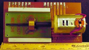
Thanks for posting the pic, straight-track. Yes, that's definitely a DC motor with a screw attached to it. In order to wire it up, you will need a switch that will enable you to reverse the polarity of the circuit and have an OFF position - maybe an DPDT-CO switch? (double pole double throw center off).
But where are the leads to the motor going on the circuit board? Can you post a pic of the back of the board? Or is it blank? Are there any engraved markings on the motor itself? It's obviously some sort of DC junction...
But where are the leads to the motor going on the circuit board? Can you post a pic of the back of the board? Or is it blank? Are there any engraved markings on the motor itself? It's obviously some sort of DC junction...
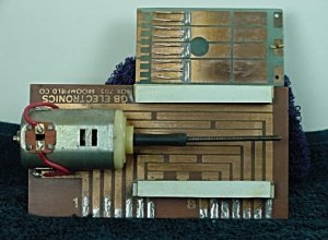
OK. Terminals 1 and 2 obviously power the motor. The remainder of the device is a distribution board. And what are the white strips across the board? And what is the additional piece of circuit board?
With a little trial and error, it would be easy enough to figure out the whole business, but you're still left with one problem: how does the screw throw a turnout? There has to be some kind of mechanism that attaches to the screw and the turnout, converting the torque of the screw to a lateral motion. Is there another piece to the whole thing, or is something missing?
With a little trial and error, it would be easy enough to figure out the whole business, but you're still left with one problem: how does the screw throw a turnout? There has to be some kind of mechanism that attaches to the screw and the turnout, converting the torque of the screw to a lateral motion. Is there another piece to the whole thing, or is something missing?
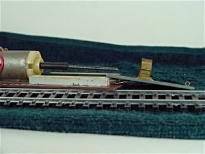
Zman, First of all, I really appreciate all the effort to help ! Here's a different yet shot showing the white strips are guides for the board of wipers to slide in. The side view of the large brass nut the screw rod threads thru and to the far right shows the eye clip connector to attach to the turnout throw mechanism. Actually quite ingenious ! My question on the wiring refers to how to wire it so it travels so far, then stops. And will only reverse and stop again when the polarity is reversed. The single pole double throws I think I can can figure OK. Joe
Attachments
 CidChase, I checked out the web site you listed and they must have bought out the old GB outfit and have vastly improved it. Going to investigate that route also. Thanks for your reply and help ! Joe :thumb:
straight-track looked up the RMC and they are 9V .40A motors recomended for 12V opperation is 2, 10 ohm 20 watt resistors in parallel 14V recomended is 2 ,5 ohm 20 watt resistors in series 18V 2 ,20 ohm 20 watt resistors in series the white bar thing's are guides. the movement can be limited by one set of contacts on the board. hope this helps
Here's what I would do if I were experimenting with the thing.
I would use two push button switches - the spring-loaded kind that return to the OFF position. One of the switches would be connected to the DC power source and terminals 1 and 2. The other switch would be connected to the DC power source with a reverse polarity and then again to terminal 1 and 2. The default position of this system would be OFF.
The advantage of the push button switches is that you would have complete control over the length of time that the circuit was in play. After a little bit of trial and error, you would know exactly how long to push one of the buttons in order make it throw the turnout, without having the screw overextend itself.
Jim Currie's contribution to this whole thing is also critically important. If the motor's rated at 9V .40A, you will probably need to add some resistors to the circuit (in parallel), depending on the output of your DC source.
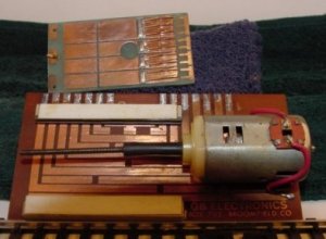
Now that I've seen all the pics, the actual motor part of the device seems very straighforward. What I find more interesting is the distribution board. I'm trying to figure out how it could be used for stuff like signals and crossings.
I would use two push button switches - the spring-loaded kind that return to the OFF position. One of the switches would be connected to the DC power source and terminals 1 and 2. The other switch would be connected to the DC power source with a reverse polarity and then again to terminal 1 and 2. The default position of this system would be OFF.
The advantage of the push button switches is that you would have complete control over the length of time that the circuit was in play. After a little bit of trial and error, you would know exactly how long to push one of the buttons in order make it throw the turnout, without having the screw overextend itself.
Jim Currie's contribution to this whole thing is also critically important. If the motor's rated at 9V .40A, you will probably need to add some resistors to the circuit (in parallel), depending on the output of your DC source.
Now that I've seen all the pics, the actual motor part of the device seems very straighforward. What I find more interesting is the distribution board. I'm trying to figure out how it could be used for stuff like signals and crossings.
cidchase
Active Member
Hi Joe,
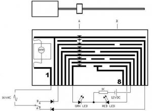
I THINK this is what you got. Y'all look it over and see if it looks
consistent with the photos, and the description on the Trout Creek
website. A couple of traces by the motor are hard to make out. I'm unsure
about the "single control wire" they describe. I let the diodes reside
at the toggle switch and not in the assembly as described.
With the SPDT toggle in Position A, the motor runs the nut (and switch board)
in to the position shown (A), and then stops. The Green LED will light.
When the toggle is thrown to Position B, the motor runs the nut out
to B, and then stops. The Red LED will light.
The other two switch poles operate in a similar manner as the board moves.
Note how the wiper springs (shown by the little fat arrows) bridge between
the board traces.
The switch linkage probably attatches to the little loop fastener in the
center hole at the end of the moving switch board.
It's my best guess.... No warranty is expressed or implied... ops:
I THINK this is what you got. Y'all look it over and see if it looks
consistent with the photos, and the description on the Trout Creek
website. A couple of traces by the motor are hard to make out. I'm unsure
about the "single control wire" they describe. I let the diodes reside
at the toggle switch and not in the assembly as described.
With the SPDT toggle in Position A, the motor runs the nut (and switch board)
in to the position shown (A), and then stops. The Green LED will light.
When the toggle is thrown to Position B, the motor runs the nut out
to B, and then stops. The Red LED will light.
The other two switch poles operate in a similar manner as the board moves.
Note how the wiper springs (shown by the little fat arrows) bridge between
the board traces.
The switch linkage probably attatches to the little loop fastener in the
center hole at the end of the moving switch board.
It's my best guess....
No warranty is expressed or implied... ops:Attachments
Here's another motor driven turnout motor at a better price if anyone is interested.
http://www.scaleshops.com/html/photos.html
I was given one of them by Bruce the owner of Scale Shops to try out.
http://www.scaleshops.com/html/photos.html
I was given one of them by Bruce the owner of Scale Shops to try out.
Cid, You are " da-man ". Your drawing is correct other than the second trace from the left goes straight up thru to the top one. I love the quality of the drawing. What program did you use to draw it ? I got these six boards for a mere pittance on E-bay so thanks to you I can now use them on a fairly large layout of mine. Great work ! Joe

cidchase
Active Member
Hi Joe, thanx, it still needs some work. The diodes aren't right in the motor
circuit, and I still think they need to be at the toggle switch. Anyhow, we're gettin'
the idea!!
It's AutoCad 2004LT :thumb:
circuit, and I still think they need to be at the toggle switch. Anyhow, we're gettin'
the idea!!
It's AutoCad 2004LT :thumb:

cidchase
Active Member
10-4, Joe, I revised the dwg on the original post. I'm still
not sure about the diodes and if there are any on the motor
itself. Maybe what they have on their website is a newer version?
not sure about the diodes and if there are any on the motor
itself. Maybe what they have on their website is a newer version?
I recently bought on e-bay six similar machines made by Mann-Made Products, Cincinnati, OH - out of business I think. The PC board layout is different but the operation appears to be the same as the two brands discussed in this thread. These are 3 position devices. AC is appled to one of three terminals depending on position desired. A fourth terminal is the AC return. There are what appear to be cotter pins (2) attached to the shuttle to provide the mechanical linkage. There are also additional contacts configured as a SP3T switch.
I have a couple of problems. First, the tubes connecting the motor shaft to the drive threaded rod are dried out and broken. Any idea where I can get small tubing? I tried heat shrink, which worked OK on one, but not on another two. Secondly, they run too fast. I'm using a low voltage variable auto-transformer - variac - to adjust voltage off the power pack AC. The motor has shut off contacts for all three positions, but there is enough interia so that when it shuts off in the center position, the motor overruns. Contact is made to reverse the motor back to the center but then it overruns in the other direction. It hunts for the off position. If i try running at lower voltage (slower speed), friction in the shuttle guides makes operation unreliable. I think I can lengthen the dead space between the appropriate traces, though. Any other ideas? I have in mind, perhaps, operating three position semaphores with these.
I have a couple of problems. First, the tubes connecting the motor shaft to the drive threaded rod are dried out and broken. Any idea where I can get small tubing? I tried heat shrink, which worked OK on one, but not on another two. Secondly, they run too fast. I'm using a low voltage variable auto-transformer - variac - to adjust voltage off the power pack AC. The motor has shut off contacts for all three positions, but there is enough interia so that when it shuts off in the center position, the motor overruns. Contact is made to reverse the motor back to the center but then it overruns in the other direction. It hunts for the off position. If i try running at lower voltage (slower speed), friction in the shuttle guides makes operation unreliable. I think I can lengthen the dead space between the appropriate traces, though. Any other ideas? I have in mind, perhaps, operating three position semaphores with these.