First Layout -VERY rough trackplan

Agatheron

Member
Nov 8, 2003
317
0
16
54
Mississauga, Ontario, Canada
Visit site
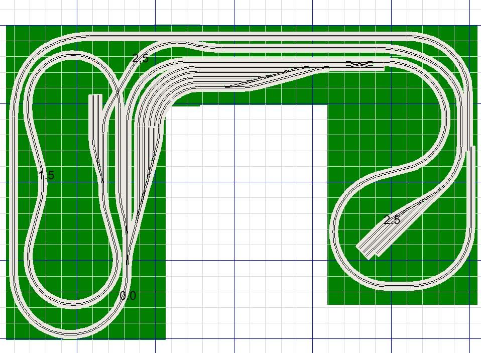
Well, I managed to cobble together a very rough trackplan using a demo version of 3rd planit and doing some screenshots. Everything, of course is subject to change, but I wouldn't mind some opinions.

I am hoping to do below-main-level staging, but that may not be possible, given the size of the layout. I may have to settle for some hidden trackage in the back... It's all done with Kato Unitrack, as it is what I happen to have on hand...

Feedback? I'd appreciate it...

RoughTrackPlan.jpg


In terms of operations, one possibility is the Duluth Western Pacific line that runs between Fort Frances Ontario/International Falls MN south to Superior WI. It's part of CN's network now, so much so that very few locos actually bear the DWP logo anymore. Operationally, some on-layout industries would include pulp/paper/lumber, but the DWP has become a major North-South coordor for CN.

Thoughts?

PS: The reason there isn't any more trackage, is that I exceeded the 100 object limit on the demo version of 3rd Plan it... :)
 

pgandw

Active Member
Jul 9, 2005
1,002
0
36
I'm assuming this is N from the elevations, and the blue lines are 12 inch squares. My comments:

1) Center aisle is a little narrow at 2ft wide. Will only fit one person in there, particularly if you have central control panel. Otherwise, great access and practical outline.

2) The branch line has all spurs pointed the same direction, and no run-around tracks. This means it has to be a strictly push-pull operation - push the cars up the branch, and pull the other ones back. May get a little boring from a switching (shunting) perspective. Add a run-around at the end of the branch at the very least, and add at least one spur that faces the other direction.

3) The branch starts from the very end of the yard, so that a train entering the branch would have to go around the main from the yard to enter the branch. The same for a train returning down the branch. Is that what you wanted? No problem if it is.

4) Is there a reason to have all yard tracks double-ended? I would consider making the closest 2 yard tracks single ended, and providing a yard switching lead (drill track) so the yard switcher doesn't foul the main while making/breaking trains.

my 2 cents, the advice may be worth less than that.
 

Agatheron

Member
Nov 8, 2003
317
0
16
54
Mississauga, Ontario, Canada
Visit site
Sorry, I should have specified... the squares are in metric because the design uses Kato Unitrack, and all their specifications are in millimetres or centimetres. Therefore the blue lines are 50cm, which works out to just over 19.5" wide... so they are a bit bigger. The centre aisle is about 40" across... with each wing being about 40" wide. It gives me broader curves...

2) The branch line has all spurs pointed the same direction, and no run-around tracks. This means it has to be a strictly push-pull operation - push the cars up the branch, and pull the other ones back. May get a little boring from a switching (shunting) perspective. Add a run-around at the end of the branch at the very least, and add at least one spur that faces the other direction.

I was hoping to add more, but the demo version of 3rd Planit ran out of objects for me to place :) Thanks for the advice though... I'd like to do a bit more with the branch line. I could put a reversing loop at the top... but again, I don't want to do the spaghetti bowl form.

As for the switching lead, again, I ran out of available track to put down on the plan. The lead is supposed to extend out beyond the double crossover. I should also have some space for locomotive servicing and such...

I would also like to add a few more passing sidings, some staging at the back, and some industries to add interest to the otherwise bare left side.

Anyway, thanks for the advice... I wouldn't mind hearing more feedback... :)
 

pgandw

Active Member
Jul 9, 2005
1,002
0
36
Based on the sizes you have given, the aisle is fine. However, I worry about access to the wings if they are up against a wall. Unless your layout is lower than most, your reach is limited to about 30 inches (75 cm). If at a low height and you are tall, you might be able to extend to 36 inches (90 cm). To have benchwork deeper than that you will have to provide either access along the "back" or access holes/hatches. A minimum size hatch has to be 18" x 18" - bigger is better - and that's assumming you are not fat (and are never going to be!). A back access aisle has the same 18" minimum requirement.

For HO, turn-back loops of reasonable radius must be accessible from at least 2 sides or have an access hatch in the middle. Personally, I will never again have an access hatch - but that's me. If the access issue is not already accounted for, it will need some serious thinking and possible redesign. Or you will be doing it after the layout is partially constructed! At the very least, you will have to narrow the benchwork beyond the turn-back curves, which will impact the yard big time.

My track planning process for small spaces (less than 12'x12') goes something along these lines:

1) Identify space and access constraints. Determine possible benchwork configurations that meet access criteria.

2) Determine longest normal train length. Iain Rice's rule of thumb to look reasonable is 1/3 of shelf length for shelf layouts. My rule of thumb for continuous run layouts is train length is no longer than the straight or cosmetically curved sections between major curves such as 90 degree turns. This length in inches or centimeters plays into everything except minimum radius. It determines run-around, staging, and yard track lengths (at least one of them). It determines distances between "towns".

3) Determine how many operators and what kind of operations you favor. I divide type of operations into 3 categories:

- through trains: trains come from/go to staging or yards to be made up/broken up. Trains run frequently across the railroad with relatively few stops or switching except at origination/termination (there are some way freights/locals). Emphasis is on scheduled operations with multiple operators. Yards, staging, and main line have priority in the design.

- spectator: recreates particular scenes for model trains to re-create. May be a bridge crossing a stream or another track, 2 trains passing in opposite directions, switching a particular industry such as a sawmill - you get the idea. Staging and realistic scenery at the particular scenes are the focus.

- way freight engineer: actually tends to be more of a short line do everything by yourself. May make up train, select and service locomotive, switch industries along the way, break up train, and put engine to bed after the day's run. Loco servicing facilities, more industries, smaller yards feature in design.

We'd all like to have all 3 in the same layout, but it can't be done very well in smaller spaces in scales bigger than N. The smaller the space and the bigger the scale, the tighter the operational focus should be.

From determining the above, you can come up with a plan that better suits what you enjoy.

I don't know it XtrakCad has Kato track libraries or not. If it does, it's a free program that will let you complete your design a little further.

Hope this helps
 

Agatheron

Member
Nov 8, 2003
317
0
16
54
Mississauga, Ontario, Canada
Visit site
The above design allows for access on each side of the wings, with the long edge up against the wall. My preference would be to extend the wing on the right hand side further into the room, but because of an odd angle in my space, it's not really feasible as it will end up blocking a door.

Oddly enough the double-wing pattern that's in the April issue of MR which I picked up today is an interesting alternative that I could adapt....

A third option I'm toying with is to construct a "donut" shape... Because I am considering building this out of Ikea's Gorm storage shelving units, it's actually possible. I drew up the above plan before realizing that my space may suit the donut style better. In terms of measurements it would be 231cm x 204 cm (7'7"x6'8") rectangle (... All the shelves would be 51cm deep, allowing for a 129cm x 102cm (4'3"x3"4") pit" in the middle of it. Additionally, I could run a branch shelf into that awkward space that would be about another 154cm (about 5 ft)... I know it would render the above plan void... but we'll see.
I'll check out Xtrkcad and see if it does Kato... :)

Thanks
 

60103

Pooh Bah
Mar 25, 2002
4,754
0
36
Brampton, Ontario, Canada
Visit site
Agath:
I built my layout on top of IKEA's Ivar shelving. That gave me much more presentable benchwork than doing it myself. It's a bit high since I didn't want to cut the shelving uprights.
I made the benchwork of L girders, placed so they sat over the top pouside of the uprights. I used the smallest wood I could find between the girders and the roadbed.
 

Agatheron

Member
Nov 8, 2003
317
0
16
54
Mississauga, Ontario, Canada
Visit site
David,

You wouldn't happen to have any pictures of that there layout would you? I'd like to see what you have done!. I have plenty of Ivar Shelving kicking around here, but used "out of the box", it's not nearly as stable as the Gorm. I would likely replace the screws that hold it together with something that can sit flat against the outer wood so I could attach fascia without too much trouble.

My intention with the Gorm is to cut the 174cm supports to approximately 122cm in height. I am debating simply purchasing the 110cm heights, but that may be a bit too low unless I choose to sit while operating... I'll have to see.