

Finally The CVR goes public
- Thread starter Will_annand
- Start date
You are using an out of date browser. It may not display this or other websites correctly.
You should upgrade or use an alternative browser.
You should upgrade or use an alternative browser.
Thanks Robin and Val.
It is just one of those pulled muscle things, I just have to find time to lay down and rest. However, I am too busy working.
It is just one of those pulled muscle things, I just have to find time to lay down and rest. However, I am too busy working.
About time I updated things here.
I have been busy with the Huntsville Dragon Boat Festival which will be held here on August 12-13.
Also the Muskoka Model Train Show which will be held in Bracebridge on August 6-7.
Also entertaining visiting dignitaries from the big metropolis of Toronto. Val said she and her mother liked their visit.
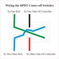
I have also found out what my problem was. I had wired the DPDT center-off switches as per the diagram below, however I was attempting to wire the track with the common rail method. The two do not mix.
I am in the process of running two wires from each block to the terminal strips on each module and then to the control panel. If I ever have any time to work on the layout, I will get it up and running.
Meanwhile I am back to copying the Muskoka Model Railroad Club DVDs.
I have been busy with the Huntsville Dragon Boat Festival which will be held here on August 12-13.
Also the Muskoka Model Train Show which will be held in Bracebridge on August 6-7.
Also entertaining visiting dignitaries from the big metropolis of Toronto. Val said she and her mother liked their visit.
I have also found out what my problem was. I had wired the DPDT center-off switches as per the diagram below, however I was attempting to wire the track with the common rail method. The two do not mix.
I am in the process of running two wires from each block to the terminal strips on each module and then to the control panel. If I ever have any time to work on the layout, I will get it up and running.
Meanwhile I am back to copying the Muskoka Model Railroad Club DVDs.
Attachments
Hi,
Your layout looks super, but you have a BIG problem that you want to correct immediately.
All rails leading to the turntable MUST be perfectly aligned to the turntable. As constructed, none of your leads are properly aligned. The spur third from the right is closest to being in line. What you want to do is get a 12 or 16 inch ruler, and place it on your turntable tracks, within the rails if possible. Move the ruler so that 1/2 an inch juts out past the turntable. Turn the turntable so that is lines up with the spot where you want your lead track to come into it. Slide a piece of straight track under the ruler, as close to the turntable as possible and line it up. This will give you an idea of where your lead track should be coming from. Once you see how the track should come in, use a piece of flex track, STARTING from the turntable, and following the line back to your existing trackage. You can bend the flex track as you see fit.
I also have some suggestions for your design, which will be in a second message, right behind this one.
Hi, I think my reply to you got sent to the next thread, so here goes again.
Your layout looks great but you have a BIG problem that you should correct immediately. Your leadin rails to the turntable must be aligned with the turntable. The rail that is to closest to being correct is the second from the right, which looks like it is just a siding. To line up the rails, get a 12 or 16 inch ruler, place it within the rails of the turntable, with 1/2 an inch jutting out. Turn the turntable to the spot where you want your leadin rail to enter (or the index if that is what you are using), and place a piece of straight track under the ruler with the rails lined up with the turntable rails. Use the ruler as a guide, moving it out as far as needed to verify that they are in line. Replace the straight track with a piece of flex track, and lay it out to your existing trackage, bending it as necessary. This will tell you where the switches will be.
In addition, I have a few suggestions. Your little set of spurs on the right side would look better if instead you replaced them with one or two or three leadin turntable tracks coming off your diagonal. You have what seems to be the leadin coming off the diagonal now, but it is in the wrong place. Draw a line from the middle of the turntable parallel to the edge of your platform meeting up to the diagonal. This should be your main lead track. You can have another parallel track to this lead going in the clockwise direction, and a third parallel track in the counterclockwise direction. These additional leads should curve just before they get to the turntable with enough space to be straight when they get to the turntable. One or both of these leads could be used to wash, water, sand and feed your locos.
George, the turntables, their leadins and their spurs are not setup yet, they are only set down for "looks and spacing". When I am done, the two on the right will be into an Engine house. As for water, sand, fuel and inspection, that will be on the line second from the left, this is the one that will lead into the turntable.
But thank you for the method of alignment, I will mark that down and when I come to finalizing the spacing I will use your method.
BTW, the Turntables are the 9" Peco kits, again, neither have been assembled.
I have to find some free time to get this done.
But thank you for the method of alignment, I will mark that down and when I come to finalizing the spacing I will use your method.
BTW, the Turntables are the 9" Peco kits, again, neither have been assembled.
I have to find some free time to get this done.
Finally I have updated the website.
I have included some photos of the structures I recieved from Robin.
At least the ones I will be using.
I have included some photos of the structures I recieved from Robin.
At least the ones I will be using.
Been a long time, and still no progress above the benchwork.
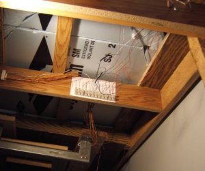
Today however I had time to do some wiring under the layout. I have the feeder wires all finished (except for the turntables and their spurs). All are fastened to the terminal strips.
Maybe tomorrow night night I will have time to run the wires from the control panel to the terminal strips.
Here is what I was looking at all day. Well, this is one of 4 terminal strip sections.
Attachments
That's old CAT3 cable ain't it?
I guess that'll take the juice, get the sleeps when I start read'n on that stuff.
Looks darn good to me... glad someone's making progress.
I guess that'll take the juice, get the sleeps when I start read'n on that stuff.
Looks darn good to me... glad someone's making progress.
Not sure what wire it is....
I know it is solid 22ga wire. It came wrapped in gray sheilding with 50 strands in it.
A friend works for a local company that installs phone and alarm systems. He gave me a seven foot section that was headed to the scrap yard.
I know it is solid 22ga wire. It came wrapped in gray sheilding with 50 strands in it.
A friend works for a local company that installs phone and alarm systems. He gave me a seven foot section that was headed to the scrap yard.
Nope not CAT3, but it is a telephone cable.
You got something to lay on and roll about?
That can get hard on the back and such.
You got something to lay on and roll about?
That can get hard on the back and such.
Ken, if I lay down, I cannot reach the table.
The frame is 37" off the ground and the foam is 40-41".
Sitting and working just over your head is not fun.
My friend who was helping me said too bad we could not put an eye in the ceiling and then raise the bench up.
The frame is 37" off the ground and the foam is 40-41".
Sitting and working just over your head is not fun.
My friend who was helping me said too bad we could not put an eye in the ceiling and then raise the bench up.
At last some progress.
I know I have not finished the Orangeville MAin Street Diorama yet, but I was given some masonite boards and wanted to see how they would look as a fascia.
Here is the results, so far. Fascia, plaster, ground foam, sand and coffee grounds.
http://www.muskokacomputes.com/CVR_Gallery01.htm
about halfway down the page.
Well, the CVR is back on track.... ALL the tortoise switches are under the track where they belong and the track is all in one piece.
Here is a once around the layout....


Here is a once around the layout....
I´m impressed
I also visited your website and spent some time there. It´s relly interesting with the story and history around the CVR
I´ll be back soon, there´s more to get for me.
I also visited your website and spent some time there. It´s relly interesting with the story and history around the CVR
I´ll be back soon, there´s more to get for me.
Thanks Berraf and Steven.
Yes, the history is very interesting. Here is a railway that started in the 1800s and had 184 miles of track. In 1980, after 100 years, all but 3 miles were still in use. Even now, over 125 years later, only 30 miles of track have been left unused, 154 miles of track is still being used.
Yes, the history is very interesting. Here is a railway that started in the 1800s and had 184 miles of track. In 1980, after 100 years, all but 3 miles were still in use. Even now, over 125 years later, only 30 miles of track have been left unused, 154 miles of track is still being used.
Will: I don't know if you've seen it, but there's an Orangeville history book that has one poor picture of the original station.
Unfortunately, it just shows one end and there's a caboose in front of it.
Unfortunately, it just shows one end and there's a caboose in front of it.
Which one is that David?
The original Credit Valley Railway Station, the original TG&B Station or the original Witch's Hat Station?
I have several pictures of the Original Witch's Hat Station. Some from books, some I had taken in the 60s/70s.
On page 18 of A.M. McKitrick's "Steam Trains Through Orangeville" (c1976 Boston Mills Press) there is a shot of CPR eightwheeler #282 in front of the original TG&B station. It was stock TG&B, similar to the Sylvan kits.