DCC decoder in Proto RDC
- Thread starter Alan B
- Start date
You are using an out of date browser. It may not display this or other websites correctly.
You should upgrade or use an alternative browser.
You should upgrade or use an alternative browser.
OK, I did one in HO, it was awhile back so I'll need to wait till I get home tonight and take a look at it. I used a DH121 (probably) and hard wired it, it was no problem. I'll get back to you again tonight with some details.
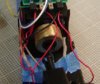
OK, I took the shell off to take a couple photos. This was just an installation to get the unit running, I still need to paint and populate the interior and add lighting. I like to use the cheapest decoders available, I don't bother with back EMF and special effects. The "combine" version of the RDC has room for a good sized decoder, in this case a Digitrax DH121. I left the pc board in for now, haven't decided if it will remain when I add lighting. I thought I might use it to mount interior lights. For now I am using just the traces which carry power from the front truck to the rear of the unit. I had to cut a few traces, as seen in the first photo. You could just remove the board and hard wire everything, I usually do.
Attachments
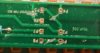
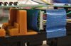
This shows the end of the pcb over the motor. You see the black and red decoder leads pushed into the pcb holes containing the track power oickup wires from the trucks. The center two unused contacts are for the headlight at this end. You would of course not use them with DCC, the white, yellow and blue wires seen, which are just taped to the pcb for now, are the power source from the decoder fo the lights. I'll probably use LED's with resistors for headlights. There are two other leads, purple and green, avaialble for other functions, I plan to use just one of them, for interior lights. While this isn't pretty, I hope it helps you.