Copper Ridge Railway under construction

roryglasgow

Active Member
Jun 3, 2001
1,223
0
36
55
Huntsville, TX USA
web.wt.net
Well, gee, guys. I guess I'm just going to have to continue building! :) I need to sit down and think about the next steps, though, before I proceed. I'm on a very tight budget, so I don't have a lot of leeway for making mistakes.

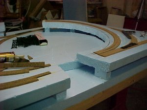
So far my total expense on this project has only been $12.75! That was the cost of the blue foam and the lathe strips that I used for the crossmembers. Everything else is recycled!

-Rory
 

Matthyro

Will always be re-membered
Dec 28, 2000
4,550
0
36
86
Georgetown, Ontario,Canada
I, for one am extremely pleased to see a caboose still in use instead of those ugly EOT units. Nothing beats seeing a train in motion so keep on gazing Rory and that gets the juices flowing.
 

roryglasgow

Active Member
Jun 3, 2001
1,223
0
36
55
Huntsville, TX USA
web.wt.net
Yeah, I really miss the cabeese. The time period of the layout won't be real recent, so trains will still use them. I want to make one of those itty-bitty bobber things...the ones with just one truck...for use on the branchline.

Eatst14, the layout is 5 feet wide and 2.5 feet deep. I was very limited on space, but this fit the available slot nicely. My original plan was to build one in 2x4 feet, but Shamus posted a nice layout that was slightly larger and featured three levels. I had to tweak the plan quite a bit, though, so that I could use what track I already had (I'm on a very tight budget). You can view the trackplan (and smaller versions of the construction photos) on my website: http://user.mscc.net/~theglasgows/index.htm

-Rory
 

roryglasgow

Active Member
Jun 3, 2001
1,223
0
36
55
Huntsville, TX USA
web.wt.net
The picture below shows all of the track laid out. I left the train at the back to give a sense of scale.

My current plan is to cut the second and third levels out of the base, then lift those sections up and place foam crossbeams under them. That would make the undersides of each level easily accessible from under the layout. Plus, cutting the pieces in the correct shape would be a cinch. Does this description makes sense? :)

Ideas? Thoughts? Suggestions?

-Rory
 

Attachments

  • const7.jpg
    const7.jpg
    46.2 KB · Views: 337

Matthyro

Will always be re-membered
Dec 28, 2000
4,550
0
36
86
Georgetown, Ontario,Canada
I remember doing cookie cutting out of a plywood base so I am sure it will work fine for you Rory. I have not had that much experience with foam. Do you use a hot wire to cut it?
 

Tyson Rayles

Active Member
Sep 25, 2001
4,310
0
36
Poverty Acres, North Carolina
Visit site
Rory how thick is the foam? Also if you cut it out you will have to go back in and splice pieces back in to support the lower track. If it's half inch thick when you raise it it may break (easy to splice back I would think). You will need lots of supports at that thickness to prevent sagging after the track is laid and the scenery is added. These are reasons I used the woodland Scenics riser kits( structual engineering is not one of my strong suits):D.
 

roryglasgow

Active Member
Jun 3, 2001
1,223
0
36
55
Huntsville, TX USA
web.wt.net
The foam is 1/2 inch thick. I use a sharp hobby knife to cut it.

My idea was to lift up the sections and support them on foam crossbeams that I will cut from spare pieces. I figure one crossbeam every 8 or 10 inches should be plenty to keep the surface stable. The area over the tunnels will be a little different, though. I will need to use something thinner so that the tunnel to the second level will have enough clearance (I'm .2 inches too short if I use the foam on the third level).

I plan on cutting the inclines from foam, then cutting the inclines into pieces that will follow the curves of the track. It won't be as pretty as the WS inclines, but this will all be covered from view by the cliff faces and hillsides.

-Rory
 

billk

Active Member
Jun 12, 2001
1,116
0
36
Marion, IA, USA
Rory – Here’s an idea I picked up from somewhere you might consider. I think it’s called the “spline” method. (Sorry for the crude drawing, I used Paint, and it’s definitely not to scale.)

Anyway, Fig. 1. represents a grade starting at point A, continuing around a curve that starts/ends at points B/C, and then levels off at point D after rising a total of 2”.

Fig. 2. is the profile of the grade – picture a side view the whole thing straightened out, with where the curve started and ended marked. Fig. 3. is a top view of the same thing. You can include the transition to/from level to grade in the profile, by the way.

What you do is take a piece of foam THICK enough to secure your roadbed to its EDGE and cut it into the shape of the profile. Then, anywhere along it that would be a curve, cut it into segments maybe 1-2” wide as shown in Fig. 2. Probably you should label these parts to keep them in the right order.

Then glue the pieces onto your layout. Locate the parts that go under curves so they touch adjoining pieces only at the corners that would be on the inside of the curve. The corners that would be on the outside of the curve are spaced apart so that the pieces follow the curve. Then fasten the roadbed to the top of the whole mess.

One problem I can see is cutting the foam so that the rails will be level with each other and there’s no unwanted dips or rises. I’d probably use a power jigsaw or whatever to keep the cuts straight.
 

eatst14

New Member
Apr 17, 2002
39
0
6
46
Greensburg
geocities.com
Ive used this before and it works well

If u find u dont have enough clearance in an area where a raised portion of the track runs over a lower section to use foam, try using thick cardboard or balsa wood just for that section. Works extremly well for hidden areas or where u dont plan to use a bridge.

Ed
Eatst14@yahoo.com
 

roryglasgow

Active Member
Jun 3, 2001
1,223
0
36
55
Huntsville, TX USA
web.wt.net
Didn't do much on the layout today. I was feeling a bit under the weather. Thanks for the suggestions, guys. I'm going to ponder these things over and come up with a plan. Hopefully by this weekend I'll be feeling a little better and can get back to work.

The picture below shows the structures in their places so I could get an idea of where the edges of each level would be.

-Rory
 

Attachments

  • const8.jpg
    const8.jpg
    16.6 KB · Views: 436

Drew1125

Active Member
Jan 28, 2001
2,975
0
36
Rory,
Just thought I'd show you what we're doing on my kid's layout...
We're using the 2" foam.
We used two layers of foam...the bottom one is for the lowest level of scenery. (i.e. water) The top layer is what I cut out as "cookie cutter" roadbed, & then added the cork. I cut risers of various sizes out of scrap foam.
I'm not sure how good this picture is, but it might give you an idea.
 

Attachments

  • mvc-005f.jpg
    mvc-005f.jpg
    53.1 KB · Views: 393

roryglasgow

Active Member
Jun 3, 2001
1,223
0
36
55
Huntsville, TX USA
web.wt.net
Tyson,

Do you need some stock cars? I've got three: two are UP (yellow) and the other is C&NW (green with yellow stripe). All are non-weathered and made by Industrial Rail. Maybe we could make a trade! Too bad I don't have anything lettered for the R&K or CPRy...


Charlie,

Thanks for the picture. That's kinda what I had in mind. Hopefully I'll get the chance to work on the layout some this weekend.

-Rory
 

RI541

Member
Feb 20, 2002
634
0
16
Winchester N.H.
Visit site
Rory,
Looks like you've been busy. I might have to get off my butt and do some on mine,but so much to do around the the house. Which is realy cutting into the fishing.

Dont let anyone fool you wood panel skies are beautiful.I have one myself.:D :D