Catapult from MechWarrior

leofirebrand

New Member
Jul 24, 2012
97
0
6
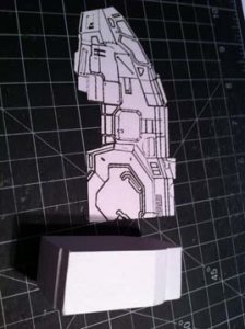
Been a fan of the Mechwarrior and Battletech franchises most of my life and while the catapult was not my favorite mech to pilot (I like my assault class) It has always been my favorite Mech design. Recently I found out that the franchise is having a resurgence and while I dont care for the fact that the new games are both "free to play" games, I do love the look and feel they have captured. Here is a picture of what the redesigned mech looks like:
MechWarrior_Online_Catapult_Concept.jpg

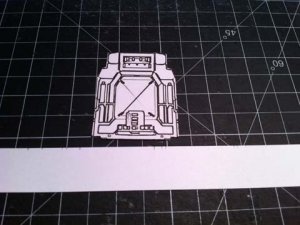
You can find more pictures along with the orthographic I am using as my blueprint here:
http://penny-arcade.com/report/edit...fully-illustrated-insanely-intricate-birth-of

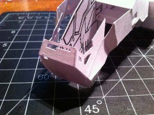
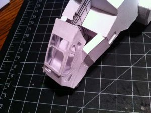
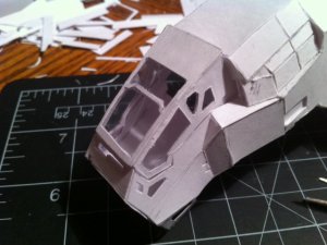
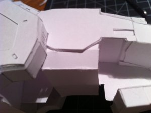
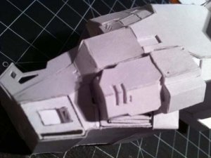
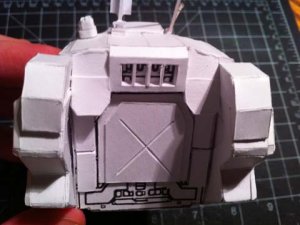
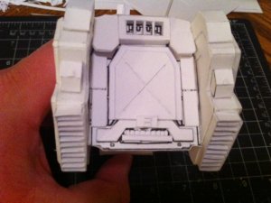
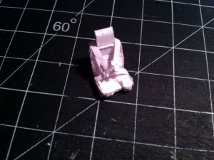
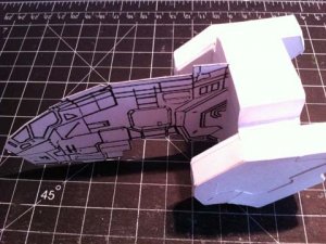
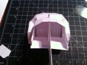
The first thing I did was start with the backside of the model as it was one of the only places where the geometry was a clear cut rectangle. Once this is in place I can scale the rest of the "plates" around it.
attachment.php


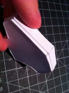
I folded the white strip around the edges of the line drawing and then glued a cutout of the side profile directly down the center:
attachment.php

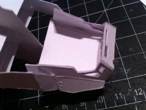
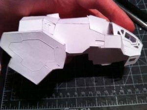
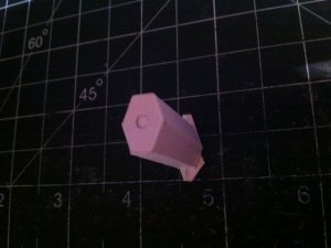
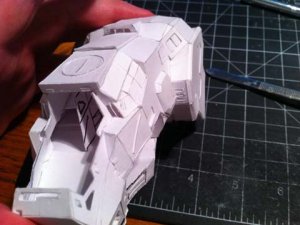
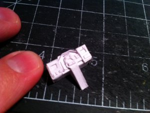
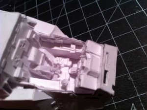
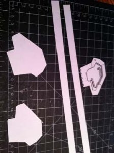
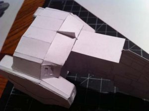
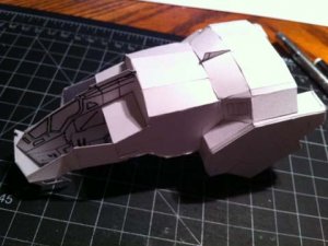
I then cutout the shoulder part that would serve as the mounting position for the LRMs. Using the cutout as a template I was able to make several more.
attachment.php

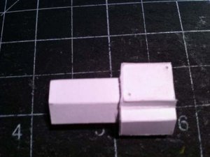
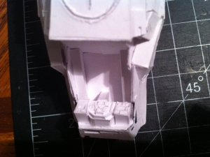
I then determine the dimensions by measuring the front side orthographic drawing and folding a strip around the edges of the template. Once that was dont I made a strip 2mm smaller and lamenated it 3 sheets of card thick. I folded this around the shoulder as well.
attachment.php

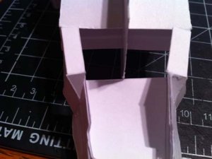
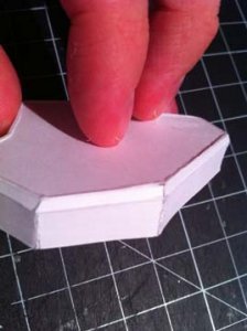
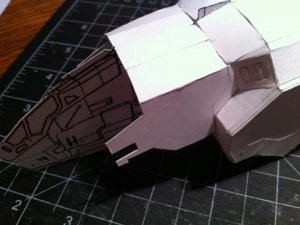
I used this smaler thicker strip as a guide and glued on thin 2.5mm strips around the edges giving it the correct tappered edge look:
attachment.php

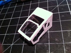
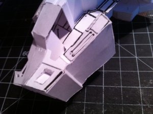
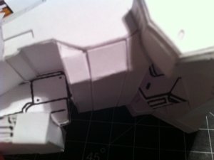
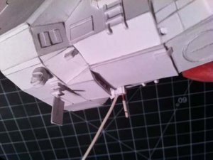
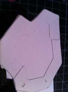
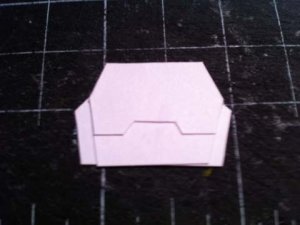
The last thing I did was use the template to cut out the detail piece for the pannels and glue that to both sides of the shoulders:
attachment.php


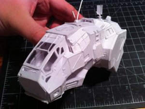
I can only upload 6 pics at a time so I will post another update right after this.
 

Attachments

  • IMG_2202.jpg
    IMG_2202.jpg
    52.7 KB · Views: 255
  • IMG_2203.jpg
    IMG_2203.jpg
    46.1 KB · Views: 255
  • IMG_2206.jpg
    IMG_2206.jpg
    46.1 KB · Views: 255
  • IMG_2207.jpg
    IMG_2207.jpg
    40.3 KB · Views: 252
  • IMG_2208.jpg
    IMG_2208.jpg
    39.9 KB · Views: 251
  • IMG_2209.jpg
    IMG_2209.jpg
    29.1 KB · Views: 253

leofirebrand

New Member
Jul 24, 2012
97
0
6
Here is the next update. I am starting by building the basic framework first and then I will go back and add all the details. I started by glueing on the shoulders uisng the profile ortho as a guide:
attachment.php

Next i used the front image and the side image to determine the X and Y dimensions of the plates and glued them on top. for the angled piece with the vents in it, I had to just had to do some trial and error till I got it to look like I wanted.
attachment.php


I then cut out one of the side paltes that was angled. obviously since it was angled It would not be scaled properly so I test fit it to the model and then glued some scrap bits to the back side until I got the shape and angle right. I then used this as a template to cut a piece. You can see the pencil mark in this photo. That represent how the piece looked in the drawing before I scaled it.
attachment.php

Here is a front shot where you can see I am glueing in strips to reinforce the model some. I glue in long strips and then cut off the excess with some small scissors.
attachment.php

Next I cut out the nose plate. This I had to resize using a combination of the front and side drawings to determine the dimensions. basically I knew I could trust the X axis on the front and the Y axis on the side even though the plate was angled. Using this I could draw and cut out the shape below.
attachment.php

Finally I glued on the side plates that make up the sides of the cockpit area. I wish I could say there was some trick I used for this but honestly it was so tricky I had to use a lot of guess work and trial and error. I dont know exactly how i got to this point, but it looks accurate to the original drawing so I am going with it.
attachment.php
 

Attachments

  • IMG_2210.jpg
    IMG_2210.jpg
    63.8 KB · Views: 246
  • IMG_2212.jpg
    IMG_2212.jpg
    33.8 KB · Views: 244
  • IMG_2213.jpg
    IMG_2213.jpg
    47.6 KB · Views: 244
  • IMG_2214.jpg
    IMG_2214.jpg
    37.9 KB · Views: 243
  • IMG_2215.jpg
    IMG_2215.jpg
    45.6 KB · Views: 241
  • IMG_2217.jpg
    IMG_2217.jpg
    49 KB · Views: 249
Z

Zathros

The way you are making this model is very informative. I used this method before I got into CAD and to be honest, it is a very good method of making models. It shows a great understanding of the object you are modeling and great imaging on your part. Very cool! :)
 

blaar

Member
Mar 9, 2008
143
1
16
Never seen this way of building. Thank you for posting these up. Also, the CAT is going to look great once you are done with it. I really love what MWO did with it. The did away with the "round" nose and gave a more boxy shape. Love it.
 

leofirebrand

New Member
Jul 24, 2012
97
0
6
Small update. I have been under the weather a bit and between elections and housework have not had much time to do much project work.

I started working on the cockpit area and basically I just cutout the left/right portion from the ortho and then scaled up the side that connects with the nose plate. Luckily because the angle was slight it meant only 1mm needed to be added to the edges. Once both sides were done i just measured the space between the left and right to get the top part of the nose cone.

attachment.php

I then cut out the cockpit area of my reference piece and layed in the walls and floors of the cockpit measureing as I went.
attachment.php

Now that this was in place i cut out small triangles and sized them to fit as seen below and the put a small strip for the sides as seen in the reference photos:
attachment.php

The cockpit hatch was alot of trial and error and I started without windows and mounted everything with masking tape to give a temporary bond while I got the shape figured out. Then i drew and cut the window out. To add the plastic windows I made two copies of each side and glued window plates in between the two. The trick is to make the windows slightly smaller so the paper can glue to paper, as clear plastic wont bond well to paper.
attachment.php

Here are two pics of the cockpit being test fit:
attachment.php


attachment.php
 

Attachments

  • IMG_2219.jpg
    IMG_2219.jpg
    59.4 KB · Views: 193
  • IMG_2220.jpg
    IMG_2220.jpg
    45.9 KB · Views: 190
  • IMG_2221.jpg
    IMG_2221.jpg
    42.2 KB · Views: 190
  • IMG_2222.jpg
    IMG_2222.jpg
    57 KB · Views: 190
  • IMG_2223.jpg
    IMG_2223.jpg
    56.7 KB · Views: 190
  • IMG_2224.jpg
    IMG_2224.jpg
    43 KB · Views: 191

silveroxide

Senior Member
Aug 22, 2007
2,036
525
113
Fayetteville NC
Your way of making scratchbuilds is something that I enjoy in watching. As a scratch builder, your techniques are different from mine but the end results is what matters and your model is advancing rather well. Keep it up and see you around the forums.
 

aleks

Member
Jul 28, 2011
122
10
18
Italy
First: this Catapult is far better than the original one.
Second: your scratch builiding method is really educational.

I try to scratch build something by myself without using CAD (in fact I don't know hot to use CAD) so I can learn a lot from you and Silveroxide
 

dnalor

Well-Known Member
Oct 28, 2011
917
186
58
Belgium Europe
:)
This looks so easy...but somehow i think this is difficult.
You have to build it also in your mind, not only with the paper.

i'm impressed..
 

leofirebrand

New Member
Jul 24, 2012
97
0
6
As always thanks for the kind words, hopefully im describing enough so other people can try their hand at scratch building by hand...though I do not recommend starting with the Catapult as this thing is testing me at every turn. Still the challenge is fun.

I also agree the new mech designs they did for MWO are far more striking then the original artwork from the battletech days.

have some updates. I built what I am calling the cowl since it goes behind the cockpit. I basically cut rectangular shapes just by eyeing it in releation to the concept art. sadly this part of the model is proving frustrating because the line drawing does not really work in 3D so I have had to make a few modifications and hopefully it still looks like the original artwork.
attachment.php

Next I started work on the underside of the model, luckily this part held really close to the orthographic. I was able to cut the parts right out and glue them with only minor adjustments to their lengths. To make the large piece that goes on the bottom I just glued a piece of card to the two side pieces and cut off the excess.
attachment.php

I then started building the belly section. This was really easy as it is not seen really well so I have some flexability in its appearance.
attachment.php

The drawing showed it did have a armadillo look to it so I glued on strips of paper to give it that effect:
attachment.php

At this point I really wanted to start to add greebles and detailing the body but I felt it would be more prudent to build the laser pods first. You can see where I am at with this. This shows how I often like to take simple shapes and then eventually I will build them up with layers to give them the disired look.
attachment.php

Thats all I have for now. I dont have much going on this weekend so hopefully I will be able to finish the whole main body. Luckily from what I can tell the body is the hardest part so the rest should not require so much quess work and trial and error.
 

Attachments

  • image.jpeg
    image.jpeg
    109 KB · Views: 160
  • image2.jpeg
    image2.jpeg
    104.7 KB · Views: 158
  • image3.jpeg
    image3.jpeg
    79.9 KB · Views: 157
  • image4.jpeg
    image4.jpeg
    73.7 KB · Views: 154
  • image5.jpeg
    image5.jpeg
    92.3 KB · Views: 155

leofirebrand

New Member
Jul 24, 2012
97
0
6
Another update today. Got most of the main body done this weekend. Only need to finish the backside and cockpit area.

After creating the basic shape of the laser pod, I used the back template you can see in my previous post as a guide for folding a strip of paper around the back of the pod. I then glued on a few extra rectangles to the upper half to look like the armor plates in the concept drawing.
attachment.php

Next I cut out the front armor plate design from the orthographic and scaled it up by about 1mm on all sides. I then glued this to the front part of the gun. You can see it placed onthe main body below.
attachment.php

Next I started adding some of the detail pieces. Most of this just involved glueing on small strips of paper. But you can see I also added the vent to the top along with the raised plates you can see in the concept art.
attachment.php

I then built the antannea arrays. I used some thin wire for the long antannea and cut off some of the plastic tubing to make it look more like the concept art. The rectangular one was real easy to use and I made it using different rectangle shapes on my stencils. You can also see I glued on some ladders.
attachment.php

I started work on the back side but still have so more to do. Most of this was really easy as I found a screenshot online that showed the backside very clearly.
attachment.php

Here is where I am so far minus the laser pod which is not mounted permanently yet as I will enentually need to paint everything. I tried to hold it at the same angle as the concept art I put in my first post. Hopefully it looks pretty close.
attachment.php
 

Attachments

  • IMG_2244.jpg
    IMG_2244.jpg
    41.9 KB · Views: 138
  • IMG_2245.jpg
    IMG_2245.jpg
    46.7 KB · Views: 142
  • IMG_2251.jpg
    IMG_2251.jpg
    51.4 KB · Views: 139
  • IMG_2252.jpg
    IMG_2252.jpg
    45.4 KB · Views: 142
  • IMG_2253.jpg
    IMG_2253.jpg
    53.4 KB · Views: 140
  • IMG_2254.jpg
    IMG_2254.jpg
    48.9 KB · Views: 143
Z

Zathros

This is one of the best ways to explain why building a model from pieces is better than just trying to fold one out of a bunch of bends. The amount of detailing and greebling here is just excellent, and you know when it's painted up, it will be even more killer! :)
 

silveroxide

Senior Member
Aug 22, 2007
2,036
525
113
Fayetteville NC
Great job on the build. It reminds me of building a model out of styrene. the same methods can be applied to paper. The only thing I would have done differently, is the small fragile stuff like the antennas and other fragile greebles, I would have saved them for last. The constant handling will make you-re glue them various times throughout the Build. Since you already got the cabin made, I will be interested as to how you will detail the interior cockpit. I will drop in now and then to check out your build and learn as you build. Enjoy and see you around the forums.
 

leofirebrand

New Member
Jul 24, 2012
97
0
6
Yeah I will agree I should not have glued on the antennae yet and I knew it was a bad idea when I did it....i just really wanted to see everything on the body. Luckily I have not had any issue yet and as of now I am done with the main body so it should be safe.

First I finished off the backside of the model. I glued some rectangle shapes to the bottom of the side panels and added some vents inside to make the jump jets. I then cut out some of the shapes from the orthographic and glued them on as accent pieces.
attachment.php

I then started detailing the cockpit. I lucked out and found a concept art online that was effectively a colored orthographic and scalled the top down perspective to fit in my cockpit. I was then able to use this as a floor plan. Everything else was done by eye using some screenshots of the catapults cockpit. Here you can see the front console:
attachment.php

I then glue the console in place and added some long rectangular pieces inside that will server as the arm rest for the pilot controls:
attachment.php

The pilot seat was again built using the orthographic concept art and since it had a top down perspective and a side perspective I had both the X and Y Axis making this really easy. I was not able to add all the detail of the screenshot as the whole thing is roughly 12X5mm and I simply cant make cuts that small with an exacto knife. I used 28pd paper instead of 110pd for the seat buckles.
attachment.php

Here you can see the cockpit in place. It's not glued yet as I will need to paint everything before I permanently attach the seat.
attachment.php

At this point I am debating if I want to add more greebling. Would love some feedback should I add more detail or would that just make it look too busy?
 

Attachments

  • image6.jpeg
    image6.jpeg
    113 KB · Views: 100
  • image2.jpeg
    image2.jpeg
    118.4 KB · Views: 104
  • image3.jpeg
    image3.jpeg
    101.6 KB · Views: 104
  • image4.jpeg
    image4.jpeg
    114.9 KB · Views: 106
  • image5.jpeg
    image5.jpeg
    107.5 KB · Views: 101

silveroxide

Senior Member
Aug 22, 2007
2,036
525
113
Fayetteville NC
As of now, the cockpit is looking good. I do not recommend any more greebles but a few details may look good, something like a paper star chart or a coffee thermos. If you are not going to put a pilot inside, maybe a flight helmet. Is the instrument panel set in place? If it is, then it is going to be interesting to see the paint job on the instruments. You are doing great, waiting for more.
 

ThunderChild

Active Member
Yea, you already have more greebles and raised detail than models 5X as big. That doesn't mean you couldn't add more if you thought it would improve on the look.

Love the cockpit! Gotta say it again: This is one of the most awe-inspiring models I have ever seen taking shape, in large part due to the fact that it's all done by hand.
 
E

ekuth

Impressive, clean work.

A Model of the Month in the making, methinks...