BUZZZ Pulsejet Powered Paper Cardstock Airplane

mbauer

Cardstock Model designer
Jan 31, 2006
58
23
18
66
Nikiski, Alaska
Nice way to start 2015, completed Buzzzzz project at 1045pm Alaska time, on 01-01-2015. 400-photos during construction.

This thread is a copy of one posted at the other paper modeling site.

After several drawings, finally hit on a workable design. This thread is how it was made.

Besides Springhill Tag 125# Cardstock, other materials used are in the following list:
1) Metal 22 gauge plate for heat shield
2) 1/4" Thick x 3" Wide wood for Engine Mount, Battery / fuel mounts, electronics, finally to add strength to model and transfer power from engine to structure
3) Fiberglass resin, hardener, fiberglass matt & cloth for wing spars
4) Back of a desk calendar (heavy duty cardstock) for laminations
5) Ceramic Paper refractory for heat insulation between engine mounts and heat shield.

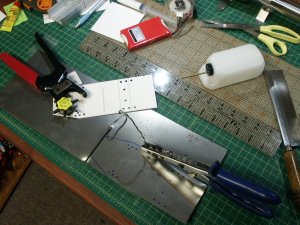
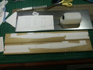
Photo 1 shows misc. items, cardstock patterns for wood metal heat shield, fuel tank.
1.jpg

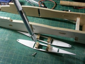
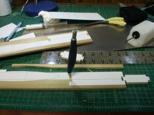
Photo 2 shows using a fiskars hobby knife to carve wood to pattern shape.
2.jpg

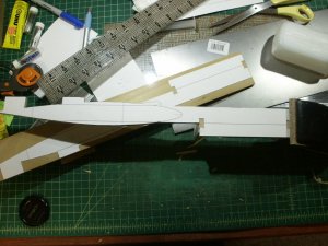
Photo 3 shows completed part before starting on second piece.
3.jpg

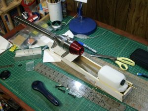
Photo 4 shows 2/3 completed wood mount system. Checking for fit. Pulsejet with cardstock heat shield pattern.
4.jpg

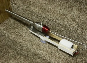
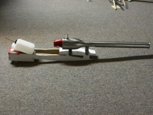
Photo 5 shows part location. Battery will lay flat under fuel tank, engine will mount to wood skid by use of screws with a metal heat shield under it. Skid still needs floor added.
5.jpg

Well lots more to follow!

Mike
 

mbauer

Cardstock Model designer
Jan 31, 2006
58
23
18
66
Nikiski, Alaska
This post will cover fabricating the heat shield, fiberglass spar lay-up, and fuel system.

The first couple of pulsejets I bought used propane for the fuel. This caused issues here in Alaska, because the pressure drops when propane gets cold. The boiling point for propane is -44 deg F. When it gets cold it doesn't boil fast enough to keep the pressure high enough. Need a different fuel type. Found a new pulsejet engine that uses regular car gasoline.

Biggest issue is finding fuel lines that can handle gas instead of most fuel types used in RC or control line models.

Metal working the 22 gauge metal plate into a heat shield means cutting. Luckily have a hand powered metal "nibbler" that can handle the task. Notice the cardstock pattern for the heat shield with bolt holes already marked.
Used the leather hole punch to make nice clean little bolt holes in the card to transfer to the metal.
Misc. items in the photos are the 8-oz fuel tank, 11.1 volt 3s lipo battery pack.

Photo 6 shows the nibbler at work, notice how I've got it trained to do everything by itself...
6.jpg

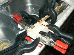
Photo 7 shows clamping the wood "power skid" using 5-minute epoxy.
7.jpg

Photo 8 shows the complete to this point power skid, heat shield (minus a few holes) and the fuel tank and fuel line. Under the fuel tank is where the battery rides. A Velcro strap hold the tank and battery nice and snug (not shown).
8.jpg

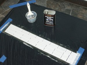
Photo 9 shows fiberglass wing-spar lay-up. Notice the cardstock paatern on top of the curing resin/hardener. Used alternating fiberglass mat and cloth for 6-layers. Total thickness when done was right at 3/32".
9.jpg

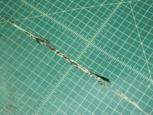
Photo 10 shows what might save someone's cutting mat. First choice for wing-spar material was some expensive carbon fiber/Kevlar cloth mix. Just thought it would be a no-brainer to cut to size using my rotary cutter on top of my $70 Alvin matt. Almost impossible to cut! after going back and forth with great pressure applied it finally cut through, the end result is many cut marks on my mat and the weave got stuck into the matt. Un-happy is an understatement! Was able to pull the weave out using my needle nose pliers, but matt still has those nasty cut grooves now.
10.jpg

Some of the issues with trying to use a pulsejet and paper are as follows:
Rudder (s) need to be located far, far away
As much of the model parts/pieces located away from the heat source (pulsejet)
Try to keep the engine as near to the CG (Center of Gravity or balance location)

After trying a couple of different designs decided to do a flying wing with the rudders located on the wingtips. About as far away from the engine as possible.

For controls decided to "mix" the aileron and elevator into a single control surface. This meant buying a different Radio Transmitter and Receiver.

More to follow!

Mike
 

mbauer

Cardstock Model designer
Jan 31, 2006
58
23
18
66
Nikiski, Alaska
Wing Construction:

Ok, spars are cured. How to shape?

Visited many boat building sites looking for an answer. Everything from carbide blade skill saws to diamond grit blades for ceramic tiles. One guy said to use a hacksaw.

Everyone said messy, messy and get ready to itch and massive clean-up issues.

Where I work, we sell tyvek suits and respirators, duct tape and first aid kits. Ok, got my choice of PPE (personal protective equipment).

My saw of choice is a little Milwaukee variable speed sabre saw. Looked for and found a diamond grit blade. Thinking that this type of saw wouldn't create such a big cloud of fiberglass dust.

Smart choice! Started with the speed at the low end to test if it would work. It did! Slowly cranked the speed up and found the faster it went the easier it was to control and easier cutting. Went overboard and maxed it out, big mistake...Like a hot knife going through hot butter, no control and it flat tore the fiberglass up.

Slowed it down to about 2/3 max speed and had the spars cut out in about 15-minutes. No major dust cloud, no big mess, and goggles and dust mask where the only PPE needed. Oh, and cut resistant gloves!

On the cut resistant gloves. I've stopped buying the thermal type and utility gloves that have great grip (plastic dipped on a knit glove). The cut gloves come in many different weights and dexterity. I use them for everything now. In other words, I don't have scratches or cut marks on my hands anymore. My favorite ones cost $6.50 a pair and are made of dynema, light weight and dexterity is great. last a long time and the protection is fantastic! Home repair, auto repair, fish cleaning, to model building!

Ok, back to the model...

Photo 11 shows wing spar test fit, before sanding and smoothing of spars.
11.jpg

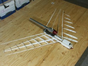
Photo 12 shows ribs, spars and engine mount.
12.jpg

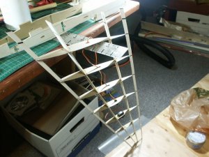
Photo 13 shows right wing rib test fit. Ribs are a single layer of Springhill Tag 125lb with a laminate using heavy card that is on the back of notebooks or legal pads (yellow paper).
13.jpg

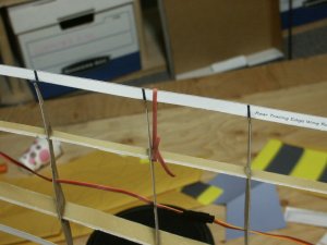
Photo 14 shows a close up. Notice how spars are a little wavy, cleaned up nicely with a diamond grit file.
14.jpg

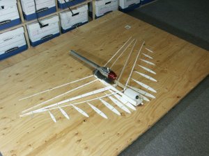
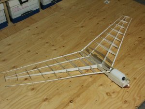
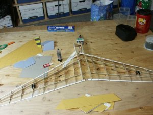
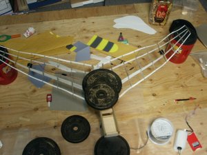
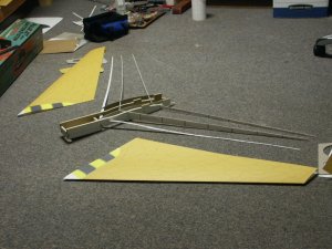
Photo 15 shows ribs in place (dry fit test) and shape of wing. Not Swept back enough. Had some future wood work to do!
15.jpg

Anyone guess yet at the paint scheme I'm going to use?

More to follow!

Mike
 
  • Like
Reactions: zathros

mbauer

Cardstock Model designer
Jan 31, 2006
58
23
18
66
Nikiski, Alaska
Time to test fit and verify servo cable lengths, general layout of control surfaces:

Not much going on here. Just basic layout and verify everything will fit, before actual installations.

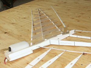
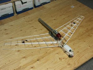
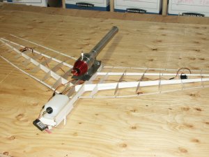
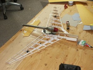
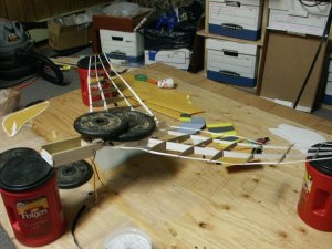
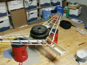
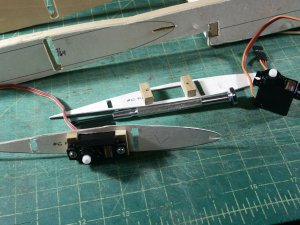
Photo 16 shows where the servos are going. Notice using a Y-cord to connect the servos. Actual finished model will use Transmitter mixing to work the Elevons (Y-cord not used).
16.jpg

Photo 17 shows the same from a different angle. Radio Receiver will be attached to the front piece of wood using Velcro!
17.jpg

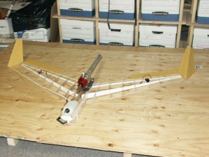
Photo 18 shows Rudder and Elevon locations.
18.jpg

Photo 19 gives big hint on what the paint scheme is going to look like. Fuselage pieces that hide the fuel tank and electronics. Fuselage doesn't have to carry much flight load, other than its own weight. All the heavy stuff is located inside the wood skid.
19.jpg

Photo 20 shows a wing skin to give a better idea of the paint scheme...
20.jpg

Next post will show wood shaping, servo mounts etc...

Mike
 
  • Like
Reactions: zathros

mbauer

Cardstock Model designer
Jan 31, 2006
58
23
18
66
Nikiski, Alaska
Wood Work:

Ok time to angle the spar openings so that the spars angle back instead of sticking out at 90 degrees.

To modify the openings will be using a Riffler File set that has 5 files with a double cut cutting surface. They are bigger than needle files and have a bend approx. 1/3 the distance from the end. Great for getting into hard to reach areas.

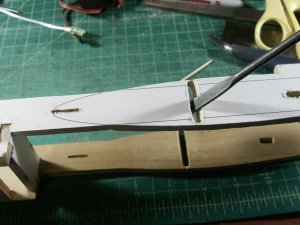
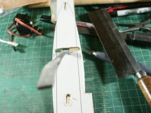
Photo 21 shows the "flat" riffler angling the main spar opening.
21.JPG

Photo 22 shows the riffler file bend. notice how great it is to use for these angles?
Yes, they can also work as a pry bar. Notice how thin the wood is near the end of the openings. Real easy to apply the wrong "prying" pressure and break the wood. Yep, you guessed it, broke one of the back spar openings...
22.jpg

Photo 23 shows my little finger twist drill. Want one? Can be purchased for $12 at your local Airgas USA, LLC welding supply. Come with the smallest drill bit sizes in the handle. Used to clean acetylene cutting tip openings. It is a Radnor part number. If you buy one, use caution when opening the drill bit compartment, the smallers sizes are smaller than a sewing straight pin, real easy to drop and loose...Till you're barefoot...
23.jpg

Photo 24 shows first servo mounted.
24.jpg
More to follow..

Mike
 
  • Like
Reactions: zathros

mbauer

Cardstock Model designer
Jan 31, 2006
58
23
18
66
Nikiski, Alaska
Time to glue the wing ribs to the Leading/Trailing edges and Spars:

For gluing to the cardstock leading edge, Alene's Turbo PVA is used. Trailing edge wouldn't stick, so converted to super glue.

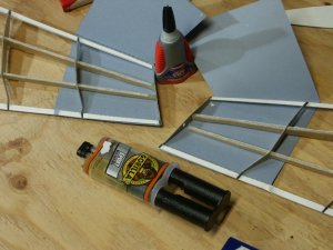
Photo 25 shows how I cheated to keep the wingtips in the proper shape when gluing the ribs to the spars. Ribs are already glued to the leading/trailing edges. Had to use super glue on the trailing edges, not to happy about that.
25.jpg

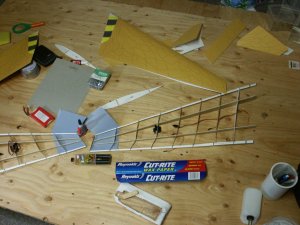
Photo 26 shows a wide angle view and the best item you can use when doing any kind of epoxy work: Wax Paper! Work great for a release on the spar lay-ups to keeping excess epoxy off of the work surface.
26.jpg

Photo 27 shows the wing positioned vertically for the actual epoxy fillets from rib to spar. Notice the double use of the plastic ruler..
27.jpg

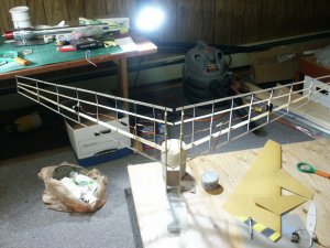
Photo 28 shows the fit test of the outer fuselage to the wing. Yes, there needs to be a final carving to the wing airfoil shape to get the fuselage to fit properly.
28.jpg

Photo 29 shows the wings fit test to the wood power skid after the wing structure has been glued (ribs to spars).
29.jpg

More to follow.

Mike
 
  • Like
Reactions: zathros

mbauer

Cardstock Model designer
Jan 31, 2006
58
23
18
66
Nikiski, Alaska
Time to epoxy the wings to the power skid.

A confession: Forgot to design the wing length to account for the thicker 1/4" wood power skid. This added a 1/4" to each side, or 1/2" total. There is a gap between the wing halves where they meet in the middle. Ouch!

Quick fix is to print a new middle piece to patch the gap.

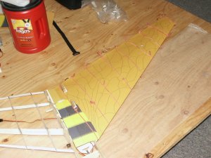
Photo 30 shows one last look at fitting of wings to wood. Without the wing skins don't realize the above issue yet. This is the last photo just before the epoxying happens.
30.jpg

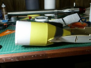
Photo 31 shows wings as epoxy is curing, notice item behind pulsejet in the background? White cylinder tube is the inside fuselage support. Gives the fuselage strength and helps keep the round shape. Sorry, about the bright LED light...Only used this photo to show the fuselage support-only photo with it in it.
31.jpg

Photo 32 shows all screws in heat shield to verify it fits with no issues. Wings are solid to the wood frame, only thing left to do is a fiberglass layup to join the spars in the middle. weight with everything on top of scale is at 3lb 3.7 oz.
32.jpg

Quick weight test is next to test how strong it is!

Mike
 
  • Like
Reactions: zathros

mbauer

Cardstock Model designer
Jan 31, 2006
58
23
18
66
Nikiski, Alaska
Structural Weight Testing:

Weight testing without wing skins. Hoping for around 10 lbs, if model weighs in at a round 3lbs 4oz, this means it will have a 3 G load limit. 15lbs will give an approx. 5 G load limit.

Some problems popped, loose!

Photo 33 shows 15 lbs being supported by the wings and front edge of power-skid. Notice the trailing edge super glue didn't hold on several ribs!
33.jpg

Photo 34 shows wing flexing but not breaking!
34.jpg

Photo 35 shows 30lb center wing section testing. You can see the fiberglass lay-up of the front wing spar connection. Front and back od spars were laid-up using 3 layers on each connection and then 2-more layers added going to the wood sides. You can also see the dark wood dowel that was epoxied in to also make sure the connection stays together = Strong!
35.jpg

Fixing /covering the wings is next!

Mike
 
  • Like
Reactions: zathros

mbauer

Cardstock Model designer
Jan 31, 2006
58
23
18
66
Nikiski, Alaska
Time to fix the trailing edge that popped loose from the ribs:

Hard time trying to figure how to clamp. Rubber bands and super glue to the rescue!

Just enough pressure using the rubberband, a small drop of superglue to hold and viola, perfect clamp for delicate work!

Photo 36 shows rubberband clamp in action!
36.jpg

Photo 37 shows rubber-band clamps holding wing skin down to ribs. Used Alene's Turbo Tacky by applying to each rib (top & bottom) front leading edge as well as rear trailing edge. Not much to see, except for the rubber-bands. Cut each band and tied them end to end to get a long "clamp", final tie was used to create the right amount of pressure. Worked great!
37.jpg

Attaching the fuselage is next!

Mike
 
  • Like
Reactions: zathros

mbauer

Cardstock Model designer
Jan 31, 2006
58
23
18
66
Nikiski, Alaska
Attaching the Outer Fuselage shell to the wing:

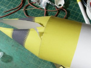
Ok, right off the bat made another mistake. Fuselage shell fit test, worked earlier with no problems. This time it ripped, bad! Had to reprint a new one.

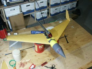
Photo 38 shows the tear!
I do not like gluing cones! Oh well!
38.jpg

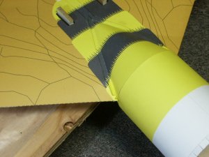
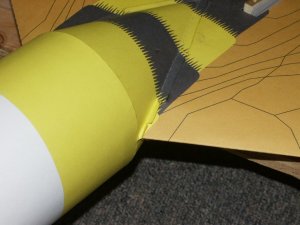
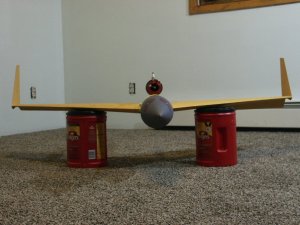
Photo 39 shows gluing fuselage top to wings. Alene's worked great once again!
39.jpg

Photo 40 shows left side getting glued.
40.jpg

Want to see what it looks like?

Mike
 
  • Like
Reactions: zathros

mbauer

Cardstock Model designer
Jan 31, 2006
58
23
18
66
Nikiski, Alaska
Ok, here it is!

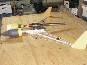
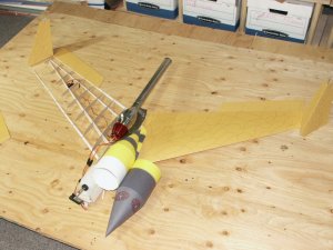
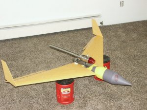
Photo 41 shows the rudders drying. Elevons have been taped on using heavy duty clear repair tape. Simple!
41.jpg

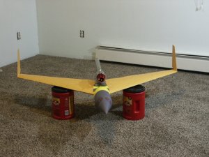
Photo 42 head on look.
42.jpg

Photo 43 shows looking down at it. Notice little servo tabs sticking through the wings? These are the Elevon hook ups.
43.jpg

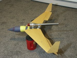
Photo 44 shows Right side view
44.jpg

Photo 45 left side view
45.jpg

Views of inside electronic mounting are next.

Mike
 
  • Like
Reactions: zathros

mbauer

Cardstock Model designer
Jan 31, 2006
58
23
18
66
Nikiski, Alaska
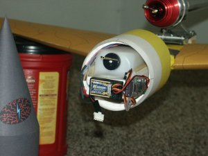
Radio Receiver and Switching BEC are shown in these views.

What is a BEC? It allows a battery to be connected to the receiver. Most models have a throttle that the battery hooks to and then from the throttle it connects and supplies power to the receiver. The more throttle you give the more juice to the receiver.

Without a throttle, if you hook the battery directly to the radio, you will fry it! It can handle 6-volts and that's it! My battery is a Li-Po that is rated at 11.1 volts.

The BEC takes the battery voltage and drops it to 6 volts or 5 Volts if you switch the jumper.

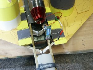
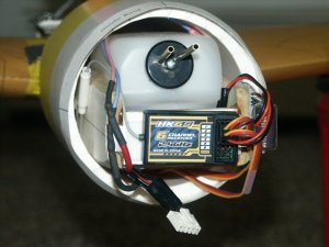
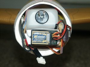
Photo 46 shows the radio and BEC. BEC is on the side mounted with Velcro. Velcro also holds the radio in place. Not much weight for either of these two items!
46.jpg

Photo 47 shows everything from a different angle. Notice tight fit for everything. White tube like device is the antenna. You can also see inside fuselage support.
47.jpg

Photo 48 is a final look at the interior
48.jpg

Total weight at this point is 3lbs 4.9 oz. Engine puts out 3.53 lbs of thrust. This models weighs less than the thrust, so yes, it can probably go vertical!

Notice I limited the fuel tank size? Engine says to use a tank three times bigger than this one. My thoughts are a quick climb to altitude and then a glide when the fuel runs out. Level flight at speed might rip the paper!

Once a pulsejet is running, there is no throttle! Wide open or it quits.

Future posts will be done as things are updated.

Thank you for looking at my recent build, hope you like it!

Mike
 

spaceagent-9

Right Hand Man and Confidant
Moderator
Jul 10, 2013
3,107
3,474
143
62
pheonix
hey! this looks great! you really know what you are doing! I can almost see it flying, I really admire your talent and skill, and of course vision of design! great job!
 

mbauer

Cardstock Model designer
Jan 31, 2006
58
23
18
66
Nikiski, Alaska
Thank you for the great comments!

Will be posting a few more pictures as the last few things are finished. Plan on doing a short video when it is running.

Mike
 
  • Like
Reactions: PaperAir

micahrogers

Moderator "Where am I, and how did I get here?"
Staff member
Moderator
Jul 12, 2012
3,772
4,639
113
Shannon GA
Great work combining three of my favorite hobbies... RC... Planes... and papermodels Good work.
 

zathros

*****SENIOR ADMINISTRATOR*****
Staff member
Administrator
Moderator
Apr 5, 2013
13,498
9,549
228
It looks like the angle of incidence is parallel with the wings chord. This means the negative pressure on the leading edge will require much much pulling on the elevons. At this point of your build, tilting the pulse jet a bit down, at the aft end could balance it out. I might try flying it on a tether, with temporary trim tabs on the rudder steering the craft outwards, away from the pole. You will find out real fast if it is going to fly, or nose down. I would point it outwards, and let it take off on it's own. It should lift off. A nice glide slope is what you want.

I build flying wind gliders, but I use a wing profile with a greater profile on the bottom, and not as much on the top. This makes the negative downward force at the leading edge nose the gliders upwards. You can discover this effect by dropping a properly balanced straight wing and watch the wing plunge to the ground.

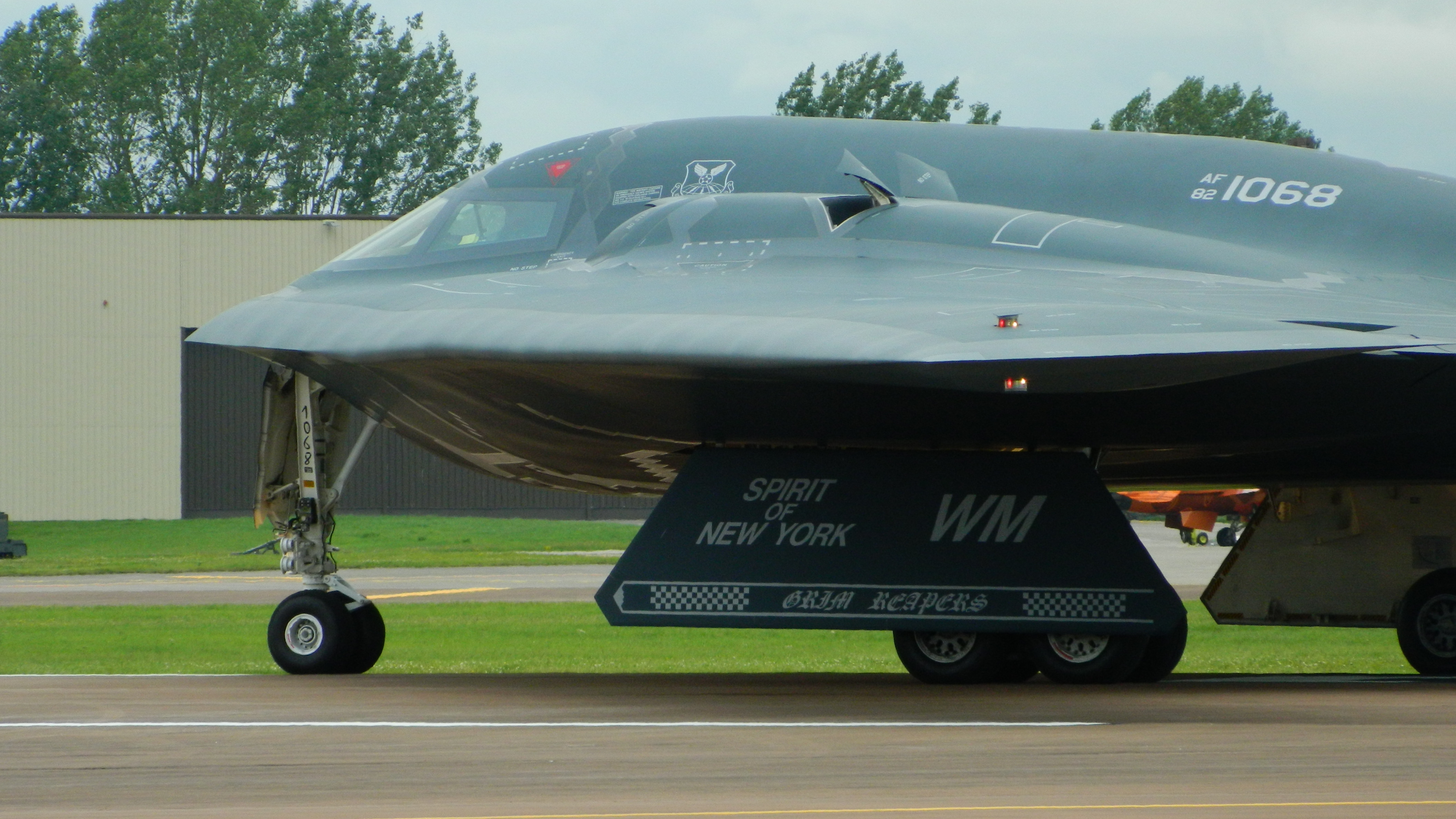
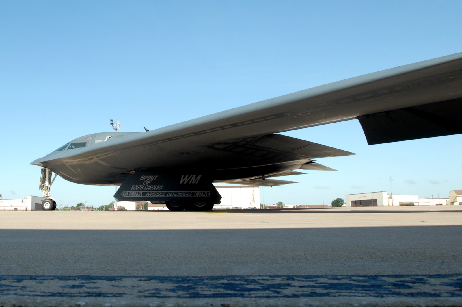
You can see the proper wing in the Stealth Bomber. The top looks almost flat! This only applies to tailless aircraft, i.e. flying wings. I also have found that 70 degrees is the optimal angle for the planform. That has been my experience with these things. I'd love to see a video of this fly! :)

82-1068-B-2-Spirit-0349.jpg

090822-F-2616H-509.jpg