

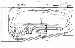
I've long felt that a track plan in Kalmbach's "101 Track Plans" would just about suit my operation interests --- emphasis on a modrately large terminal in which to make up and break up trains. I can't find the book just now, and don't recall the plan number, but it was called "Frisco". The track plan below is my version of it, changed, not only to fit my space, but to add staging tracks, and to suit 1880's rolling stock --- small locos, small cars, short trains, relatively sharp curves, and #4 turnouts.
It wound up being essentially 2 circles of track on which 2 trains could be in constant run mode, although I'll seldom if ever do that. I'll make up freight trains in the yard and run them either east- or west-bound around to the "junction" at the top, and from there onto the outer track. After a few laps around the track, if I feel like train watching, the train will be parked on the appropriate staging track --- to possibly later reappear as an inbound freight. Passenger trains will be through. That is they'll come out of staging and stop at the larger station, where they may pick up or drop off cars before proceeding back to staging. The staging will hold 3 trains in each direction, leaving the thru track open.
Minimum radius = 22" plus transitions. Drawn for Atlas #4 (code 83) turnouts.
The upper station represents a "junction" with the right-hand track from/to staging. The left-hand track to staging will be visually disguised as an industry lead.
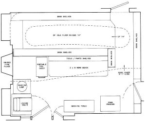
Yes there's a duckunder, but it's over 5 feet high, so isn't bad. I'll also show you the substucture of the layout, and a sectional view to explain all that.
This layout won't be started for a while yet, but unless I get brighter ideas in the mean time, this is probably close to what I'll build. I welcome all critiques. Now's the time to hear them. Before I start.
It wound up being essentially 2 circles of track on which 2 trains could be in constant run mode, although I'll seldom if ever do that. I'll make up freight trains in the yard and run them either east- or west-bound around to the "junction" at the top, and from there onto the outer track. After a few laps around the track, if I feel like train watching, the train will be parked on the appropriate staging track --- to possibly later reappear as an inbound freight. Passenger trains will be through. That is they'll come out of staging and stop at the larger station, where they may pick up or drop off cars before proceeding back to staging. The staging will hold 3 trains in each direction, leaving the thru track open.
Minimum radius = 22" plus transitions. Drawn for Atlas #4 (code 83) turnouts.
The upper station represents a "junction" with the right-hand track from/to staging. The left-hand track to staging will be visually disguised as an industry lead.
Yes there's a duckunder, but it's over 5 feet high, so isn't bad. I'll also show you the substucture of the layout, and a sectional view to explain all that.
This layout won't be started for a while yet, but unless I get brighter ideas in the mean time, this is probably close to what I'll build. I welcome all critiques. Now's the time to hear them. Before I start.

")
