Airwolf Beta builders wanted

silverw

Member
Mar 15, 2004
104
0
16
73
Saskatoon, Saskatchewan
members.shaw.ca
Part #12

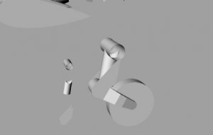
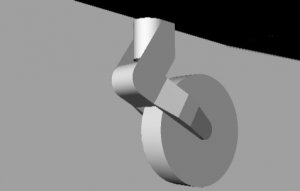
No, Will, your numbers are just fine! ... It was me.

On second try, I had the part upsidedown, inside out and rolled the wrong way; other than that, I had it right! ... and it STILL fit pretty good!!

Just give me a big square plug and I'll see if I can get it in a little round hole!

...Bill
 

Darwin

Member
Sep 26, 2005
317
0
16
78
Idaho Falls, ID
By the grace of a horrible weather report and an accident yesterday involving a site bus, our management decided to give us a snow day today, and extended it to include us townies....the first time that's happened in my 39 years here at the Idaho National Laboratory. The forecast snow didn't happen, so it will probably be the last time it happens, but hey, take whatever opportunity comes one's way. I got some more building done today, and have some pics to share.


Darwin

Member
Sep 26, 2005
317
0
16
78
Idaho Falls, ID
William, all things considered, the parts fit on this model have been great. However, there is really no substitute for a good line drawing to show how things go together. Putting on the rotor drive shaft cover was easy. I cut a length of bamboo skewer to fit the part, formed the cover around it, then split the bamboo lengthwise and glued it to the inside of the cover to both hold it's shape and keep it rigid. The gearbox, though, was in real danger of becoming a spitwad before figuring out how the assembly fits together. I made the mistake of initially building the vertical stab with a spar in it....the part needs to be flat in order to fit the gearbox on it. I have some pics of the assembly that I haven't uploaded yet, but am including these in hopes it may help Yaniv (if he hasn't made any progress since his last post).


William, I hope you have some instructional info for the landing gear ready to give us....I expect they may be needed soon.
 

Willja67

Member
Feb 12, 2005
154
6
16
44
Grantsville,Utah
Lousy instructions on my part

I'm sorry I didn't include good instructions on the last half of the model. I still have the revisions to send to most of you guys, and a set of diagrams on the landing gear will be included with the revisions.

I know it's my fault for not showing it well in the instructions but Darwin you built the exhaust nozzles wrong. Piece 13 was supposed to go inside 14. Again I take all responsibility for it as I didn't provide good instructions. My plea in the last post for you guys not to cuss me too bad still applies.
 

Darwin

Member
Sep 26, 2005
317
0
16
78
Idaho Falls, ID
If that's all I manage to get wrong, this build will be a miracle. Here are a few more photos of the rear rotor assembly.


OK, Rick, it's about time you post some pictures of the main rotor head.
 

Willja67

Member
Feb 12, 2005
154
6
16
44
Grantsville,Utah
Okay the revisions have gone out(hopefully) to all the beta builders. If not email me and let me know(possibly I typed your email wrong).

To Darwin the tail rotor looks awesome. I'm glad it worked out well. In my last post I took responsibility for bad instructions on the exhaust nozzle, well I went back and read the instructions I sent out and they did say that #13 went inside #14. As far as not providing good instructions on the gearbox I did muff that up.

As for the main rotor, it probably requires more than the diagram I sent with it. I did not provide any way to attatch m6 to the rest of the rotor assembly. On the real helicopter it looks like bolts go between the flanged parts of the piece through the blade and that there are bushings to damp out the vibrations and also provide the seperation. I did not include the equivalent of the bushings in the design so you all will have to make spacers to fit between m6 and the rotor blades.
 

Willja67

Member
Feb 12, 2005
154
6
16
44
Grantsville,Utah
Looks great! I'll send the email right now.

I don't show it in the diagram that you have in your picture but there are control rods that go between the arms of pieces 2 and 6. just use some narrow gauge wire for that. Also the lower portion of the rotor assembly is rotated slightly from the upper portion(somewhat visible in the diagram).

If my eyes are working right it looks like you have the landing gear already assembled and are very close to done with the model.
 

silverw

Member
Mar 15, 2004
104
0
16
73
Saskatoon, Saskatchewan
members.shaw.ca
Rotor

Thanks Will...

I would have guessed that the control rods went between part #4 and 6, or is that what you meant.

Took a guess at the nose gear...not sure if it is right.
I'm at work right now (SHhhhhuussshhhhh).... so I haven't seen your email yet.

.Later....Bill
 

Willja67

Member
Feb 12, 2005
154
6
16
44
Grantsville,Utah
Yeah you're right Bill it is 4 and 6. As for the nose gear it's just a slightly scaled down version of the main gear without the attatching bar on the top.
 

Bowdenja

Active Member
Sep 26, 2005
485
0
36
67
Madison, MS
Hey Guys this is neat! Looks like Will got a hit copter on his hands and y'all are showing that beta builders turn out some great "white" (Ha) stuff!

Congrats Will!
 

Willja67

Member
Feb 12, 2005
154
6
16
44
Grantsville,Utah
Thanks Bow. I guess we'll find out if it really is a hit when it first appears on Nobi's site. I hope it doesn't happen (and probably won't) but it would do my ego well if we locked up Nobi's site cause so many went to download it. I'm just dreaming in any case.

For the beta builders I am going to pm you all an evaluation thingamajigger soon about the model (fit, appearance, improvements needed). So please be thinking about the problems you ran acoss and what needs to be done to fix them.

By the way the main rotor mast is angled five degrees forward(see the other airwolf thread).
 

silverw

Member
Mar 15, 2004
104
0
16
73
Saskatoon, Saskatchewan
members.shaw.ca
main rotor

OK... 5 degrees ahead....(for the next one)...cause this one is already glued in at 90 ... darn..I had that 3-way that showed that, too!!

rotoralign7xh.jpg


Thats why the long stick!!(trimmed later) The really "heafty" roll(post #48 ), supports the rotor shaft, and makes the orientation independant of any "bumps" in the fusilage, at that point!
Of course, the rotor is free to turn...or be removed...(YaaaAAA...Models that "DO SOMETHING!!")


The original stab at the landing gear turned out like this (nose gear) Actually, Will...I prefer the original design for the landing gear.... the "revisions" one is just about in pieces,... by the time you cut it out! (IDEA!)

nosegear29lz.jpg
nosegear36kn.jpg
 

Willja67

Member
Feb 12, 2005
154
6
16
44
Grantsville,Utah
Okay original it is unless the rest of the test builders say otherwise(that means we want to hear from you).

Just a question Bill; Is the picture on the right your final assembly of the nose gear? Meaning is it already glued?
 

silverw

Member
Mar 15, 2004
104
0
16
73
Saskatoon, Saskatchewan
members.shaw.ca
Nose gear

Ya, Will...

That particular one is glued. (But, others are waiting...just off stage!!)...WHY??

Because of the size..it's pretty hard to get the main support, to the shape required.......(IDEA!)
I'm using 67# card...so it's pretty flimsy...110 probably better
 

Willja67

Member
Feb 12, 2005
154
6
16
44
Grantsville,Utah
Unfortunately you put it together wrong. Hopefully these two images will clarify things.

As you can see the nose gear is practically identical to the mains except that I cut off the top of it. If one were to build this model as a "flying" model the gears could be built retracted. Since the nose gear is covered by doors after it retracts I didn't feel the need to duplicate the retracting feature. I'm thinking that the piece you glued to the wheel might not be necesary due to the small size of the landing gear. Tell me what you think.

Perhaps the best thing to do is go back 2 pages in this thread and look at the picture of the real thing. It shows the nose gear to good advantage.

You know the perfectionist in me keeps looking at that picture and realizing that I could make it look a lot more like the real thing than I have.
 

Attachments

  • main.jpg
    main.jpg
    11.3 KB · Views: 79
  • nose_gear.jpg
    nose_gear.jpg
    14.1 KB · Views: 71

Darwin

Member
Sep 26, 2005
317
0
16
78
Idaho Falls, ID
Bill, thanks for keeping me from being the only one to screw up.....makes me feel better for putting on the main rotor hub upside down. At least the sucker leans five degrees (just don't ask me if it's the rotor shaft or fuselage that's doing the leaning). As you say....next build......
 

silverw

Member
Mar 15, 2004
104
0
16
73
Saskatoon, Saskatchewan
members.shaw.ca
gear

Ok, Will... now I see what you intend the parts to be....BUT...

that then is like your revision design, gear parts...

I don't think think it is buildable....because if you look at the part which should attach to the wheel....you would end up with 5 little separate "bits" as soon as you tried to fold it..... or am I still missing something?

Why not just use "heavy card" to make that part? (IDEA)
The printed part could still be applied to the "heavy card" for detail or whatever.
 

Willja67

Member
Feb 12, 2005
154
6
16
44
Grantsville,Utah
You may be right Bill but I think there is still some confusion here. Lets try numbering the parts for the nose gear.

In the last set of pictures that you posted we'll use the one with all the parts of the nose gear layed out and start in the upper left corner. The cylinder is #1(the hydraulic shock absorber), next is part #2(the bracket that mounts around the #1), then #3 (the fork that holds the wheel), #4 (is the interior of the fork) and mounts on the wheel(#5) just like you have it, but then those 2 parts are mated to #3 with in such a way that #4 is almost totally concealed. #4 is perhaps a "feel good" piece that due to it's small size and the fact that the wheel hides most of the inside of the fork(#3) that it might just be better to forget it.

I have been looking at the nose gear in the picture a few pages back and you guys(Darwin and Bill) assembled the nose gear almost exactly like the one in the picture(with the exception of #4 cause there is no equivalent). This post is almost worthless casue I'm going to redesign the nose gear today. However since the mains are still the same and this applies to them as well it wasn't a total waste.