cidchase
Active Member
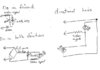
The original problem was unexplained burning
of the LED across a loco motor.
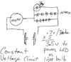
We learned from Fred that the LED's PIV is only 5V.
I think krokodil was only trying to say that if a high
reverse voltage was causing the problem, that a
series diode would not protect the LED as well as a
parallel one.
Still unsure about the inductive kick (flyback) causing
the problem, but I think it's possible.
goin' back to :sleeping: :sleeping:
of the LED across a loco motor.
We learned from Fred that the LED's PIV is only 5V.
I think krokodil was only trying to say that if a high
reverse voltage was causing the problem, that a
series diode would not protect the LED as well as a
parallel one.
Still unsure about the inductive kick (flyback) causing
the problem, but I think it's possible.
goin' back to :sleeping: :sleeping: