Adding LED's to your locomotive! WARNING!

Hello Everyone:

Last week I baught a Golden Glow White LED. There is a warning and fix I must tell you. If you use DCC, you can skip it.

I burned out the LED after 10 runs on the layout. Here is the problem I have found. I wanted to solved it before my shippment of new ones comes in!

I used a 1K (1000 Ohm) resistor to drop the voltage. According to my DVM set on DC voltage, it read 1.5v. Which is in the safe rang of operating. Checks out ok!!!

Then I switched the DVM to AC. It read 4.5vac and climbing. The LED started to smoke (used a cheap red LED for the test)! Not GOOD!!!

SOLUTION:
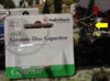
I added a 100pF cermic disc capacitor across the terminals. The DC stayed the same. The AC however never changed! No matter what the throttle was, it stayed at .05vac with the cap installed! This was within range of the LED!

It's a cheap investment. The caps are $0.99 at Radio Shack. The catalog number is 272-123. I baught out the entire stock of them. I may also try replacing the resistor with a 1.5k.

I understand alot of people are going to LED's on their locomotives. They are suppose to last forever! If you are having burnout problems, try this solution. Even if you don't. This is still a good and cheap investment!

Andy
 

Attachments

  • capled.jpg
    capled.jpg
    8.7 KB · Views: 367

shaygetz

Active Member
May 2, 2003
3,612
0
36
64
www.freewebs.com
Do you still leave the resistor in the circuit? I use 470 ohm 1/4 watt resistors on my 1.5v 2mm super bright LEDs, they make for a very bright death ray on my diesels (one in each socket on my Athearn GP35/7s) with no apparent problems so far. Where would the AC voltage come into play in regular ops?
 
Q&A's

I do still leave the resistor in the circuit. This is a must! The output of the thottle is 0-18v. An LED operating rang is usually 1.25v- 2.5v without a resistor. The resistors are a 1/4watt.

Where's the AC coming from? Can you believe your thottle's powerpack!!!:eek: Put a voltage meter across those terminals. You will be suprise on the amount of AC. The reason for this is poor regulation in the power supply.

Another place where AC comes from is the motor in the locomotive! Have you ever taken a motor and connected it to a meter? Then spin the center peice. The meter will deflect voltage! (A simple generator!)

Make sure you put the cap after the resistor and parelle to the LED.

Not to worry all you DCC users. Because digital electronics considers AC as "noise" or interference. There is very good regulation in those power packs. Note: Problems with DCC, check for AC!


Andy
 
Hi andy,
With a 1K resistor (brown-black-red) in series, the circuit
current is limited to 16mA (@ 16V either AC or DC).

Even if you have an AC component in your track voltage
(not sure how) the reverse voltage does not generate
current in the LED, up to the breakdown voltage.

Are the voltage measurements you listed taken
directly across the LED?

It's an interesting problem, seems like somethin'
odd is happening.

:) :) :) :) :)
 

ezdays

Out AZ way
Feb 3, 2003
6,339
0
36
Arizona
bigbluetrains.com
Andy,

The AC is coming from a poorly filtered DC supply. You should be able to take out the AC ripple by using one large capacitor across the power supply output. Although you can measure the AC with a meter, you cannot tell the real nature of it without seeing it on an oscilloscope. I used a scope on a couple of power packs that came with some sets I bought when I started up, and they were bad, no filtering or regulation at all. The problem is that you cannot use a large electrolytic capacitor on an output that reverses polarity.

The AC component sits on the DC and does have peaks that are higher than the DC. The small capacitor you a using will filter these ripples out. The larger the capacitor, the better the filter.
 
Bad power supply!

Don:

You are right about the cap but those Athearn locos have very little room!:eek: I did find a problem with the power supply. It's an old MRC. The filters they use are metel plate with paper as insulators agains the wall! I see the paper is bad, so bad filtering. I will be adding .01 microFarad caps in it's place. Another trip to Radio Shack next weekend!

I am not going to buy a new because the next layout will be DCC. I might start DCC now, but the cap fix should be ok.

Andy
 

ezdays

Out AZ way
Feb 3, 2003
6,339
0
36
Arizona
bigbluetrains.com
Andy,

I opened up one of these cheepie power packs that came with a Bachman set and there were no capacitors inside, just some diodes for rectification. a .01 mfd might not be big enough at the power pack if you have any load at all. A 100 mfd electrolytic would be better, but as I said, they are polorized and will blow up if you reverse the voltage. One trick you can do is to take two electrolytics and tie their negative leads together then take one positive lead to one terminal and the other positive lead to the other one allowing you to reverse the polarity without blowing them up.
 

ezdays

Out AZ way
Feb 3, 2003
6,339
0
36
Arizona
bigbluetrains.com
Andy,

Read my post again, the part about using two polorized caps tied together. That is a trick you can use on reverse voltage circuits. No kaboom when you reverse the voltage if you do it the way I said, honest.:thumb: The connection between the two caps does not get connected to anything. Just be sure the positive leads are connected to the power supply output.
 

jon-monon

Active Member
Aug 15, 2002
4,590
0
36
59
Cobblers Knob, IN
www.2guyzandsumtrains.com
The problem is that the power supply is unregulated. I would be surprised to find a power supply of this type that is regulated. Even with a modern PWM or transiostorized throttle, why would they regulate it? The safe operating voltage should be 1.5 X the AC on the secondary of the transformer. 1.5 X the measured DC out put is probably safe. I say measured, not specified, because on an unregulated power supply, it's customary to rate the voltage at what it may be safely (reliably) regulated to. So, typically a "15 VDC Unreg supply" will measure 20 or 22 VDC on a meter, and several volts AC.

I don't know why the "AC" on that particular power pack is climbing, it should be very stable. It may change if you have a train running while you are measuring it, as increased load = increased ripple. Like Don says, if you want to really know what''s going on, you have to get a scope on it. You would then find, it's not really AC, as polarity doesn't change, rather it's DC variying at an AC rate (aka ripple).

Since a scope tends to be really unhandy to have around, you can get a rough idea what the ripple is doing, and every time I've verified this with a scope it actually quite accurate, but roughly you can divide measured AC by 2, then add that back to measured DC to get peak voltage. Ex.:

DC measures 18 VDC
AC measures 5 VAC

5/2 = 2.5, 2.5 + 18 = 20.5, 20.5 is probably close to the peak the diode will see.

As mentioned, you may have problems with flyback from the motor. I'd be surprized if it's enough to burn an LED, but never say never. In a unidirectional motor control circuit, a diode across the motor is often used to shunt the flyback the protect the circuit. I've seen RCs used on bidirectional motor control. Normally this is placed across the motor, but perhaps the same has been accomplished with the cap across the resistor that is in series with the motor.

In any case, it's good to point out the fact that you may not have reliable LEDs if you select the resistor based on the specified maximum output of the power pack.
 

ezdays

Out AZ way
Feb 3, 2003
6,339
0
36
Arizona
bigbluetrains.com
Jon,

I agree, it would be surprising to find a supply of this type that is regulated, especially since they don't even bother to filter it. But for those that aren't familiar, a regulated supply can be a variable supply as well, just that the voltage remains where you set it, even if the load varys. With an unregulated supply, the output may be set at 16 VDC on the meter without a load, but add one loco and it drops to 12 volts. Add a second one without changing anything, and it may drop another few volts. This should be easy to see simply by watching the speed of a loco. As you add or take away another one you have to change the throttle to compensate. As you said, the AC one measures is a result of the ripple sitting on the poorly filtered DC. Again, this will increase as the load increases.

I have a couple of MRC Tech 350's and the output is regulated and filtered. The only thing is that they use pulse modulation to change the DC output. The peak is constant, the output consists of short pulses further apart for slow speed, longer pulses closer together for fast speed. In reality, athough not DCC, it is a digital output.
 

jon-monon

Active Member
Aug 15, 2002
4,590
0
36
59
Cobblers Knob, IN
www.2guyzandsumtrains.com
Interesting on the Tech 350, Don, I was going to design my pulsed DC supply using unreg. I wonder why they use regulated DC? I've worked with highly precision pulsed DC motor controls that just use unreg. I guess they (MRC) uses regulated DC becuase the motor(s) is an "unknown" variable to the designer. Do you know what frequency it runs at Don? I was going to go slightly above audio, maybe 25 K.

I was also thinking it would be nice to have an adjustable voltage, so you can use a higher starting voltage with a narrow pulse, like 35 or 45 VDC at a few % duty cycle, to get a loco to creep really slow. maybe manually adjustable (danger danger danger! :D ), or automatic.
 

ezdays

Out AZ way
Feb 3, 2003
6,339
0
36
Arizona
bigbluetrains.com
Jon,

The pulses are square wave and are pulse width modulated rather than frequency modulation. The rep rate was very low as I remember. I have my data written down somewhere but I can't find it right now. If I put it somewhere for safekeeping and is now really, really safe,.:rolleyes: I'll do it again. It won't take but a few minutes to do.

I say the output is regulated because the level didn't change much with load. I think it would be difficult to allow the level to stray when you are trying to change the speed with pulses.

I should have time later today and I will confirm what I just said.
 

krokodil

Member
Nov 20, 2003
218
0
16
Austria
www.railfilm.net
Hi everybody,

the reasons for AC components on the cheap power pack output can be a underdimensioned transformer, which together with the tracks and the motor can oscillate (not very common effect but I saw few times).

The second reason is the motor. Many modern motors tends to create lot of back EMF which is an AC current (typical for the older MDC and Athern motors). In Europe most of the motors are blocked with a small capacitor (around 0.1 uF and two coils in series). This AC can go up to many MHz (you can listen them on TV set or on you Radio (usually not in FM range as they use different detectors). On the cheap packs the internal impedance is to high to compensate the back EMF which appears with full power on the tracks and inside of the locomotive. You cannot usually help in such cases (except to forget this power pack).

On the high end power packs like, MRC and other stuff the reason of AC output can be the internal regulation, which tries to compensate the power losses and is usually adjusted for a straigthforward DC load (resistor). The layout with locomotives never works as a resistor so the compensation does not work properly and the whole output starts to oscillate (depend on internal components the frequency may change from few hundreds of Hertz to many MHz). On recent units there a separate compensation for DC and AC components in the feedback path.
These power packs give you an excellent performance.

It is also very important to use heavy wires from power pack to tracks, as the load compensation will not get correct values if you have voltage losses on those wires (sometimes few millivolts make a sense). :)

Sorry for my English...
 

ezdays

Out AZ way
Feb 3, 2003
6,339
0
36
Arizona
bigbluetrains.com
ET,

You did fine with your English and your explanation. This subject is of interest to me because this is one of the first questions I posed on another forum only to be piled on by a few that thought I had no right to think about such an archaic technology as DC.

Jon and others that might be interested,

I made a few measurements on my Tech 350, the same ones I made a year ago. I found it quicker to redo the data than to look for my notes.:eek:ops:

Anyway, the bottom line is that the MRC is a very stable and well regulated unit. Rather than a variable DC output, it uses pulse-width modulation. By that I mean that it puts out a series of pulses, the narrower the pulses, the lower the effective DC to the rails, and the slower the speed. As you turn the throttle, the pulses get wider until at full throttle, the output is steady. The output changed little with load meaning you can switch another loco on to the tracks without the other ones slowing down. The output was also very clean, no traces of AC ripple at all.

I made the measurements with a meter and an oscilloscope. The 350 has momentum and breaking and it was neat watching the output steadily go from zero to full as you press "start", and slowly go from full to zero when you pressed "break". I've attached my data in the event anyone is interested.

Incidentally Jon, I thought about building my own units, but found these 350's on sale at a LHS and figured I couldn't make as nice a looking unit that worked as good, even though I had most of the parts.
 

Attachments

  • mrc 350 data.jpg
    mrc 350 data.jpg
    28.5 KB · Views: 291

jon-monon

Active Member
Aug 15, 2002
4,590
0
36
59
Cobblers Knob, IN
www.2guyzandsumtrains.com
So, the frequency is at 74 Hz? Hmmmmmm. I wonder why they use it in the audio range. I guess the motor is not capable of making sound at that low of freq. The PWM circuits I've worked with are above audio range. Too low of freq. allows the field to collaps between cycles and the motor heats up. At higher freq., the motor runs more efficiant than straight DC and actually runs cooler. Upper audio range drives everyone crazy :D

I agree, you can get those at a very reasonable price. The main reason I want to build one is to learn, maybe save a little money, and to maybe have an improved product.
 

ezdays

Out AZ way
Feb 3, 2003
6,339
0
36
Arizona
bigbluetrains.com
Jon,

I think your thoughts on sub-audio frequency is correct, otherwise the humming would drive you up a wall. I would think at the higher frequencies, the duty cycle would be too short to get any decent resolution, especially if you take into account any stray capacitance.

I have just about everything I need to build a power pack and was going to do that just for fun, but when I saw those 350's for less than $65 each, I couldn't resist. I still may, but for now I will concentrate on learning about how to build a layout and run trains.

If there is anything else you want to know about the MRC packs, let me know.
 
F

Fred_M

Well, isn't a LED still a diode. The ones I use have a 5 volt PIV which I thought meant they could safely block AC, or ripples, or pulses up to 5 volts in the reverse direction. So if this is being exceeded wouldn't a 1n4001 in series on the cathode side also work to shield the led from the AC? You could also set up a LED array like constant lighting circuit uses and run the LED off of that too. FRED