

1st handlaid turnout!
- Thread starter Freelancer
- Start date
You are using an out of date browser. It may not display this or other websites correctly.
You should upgrade or use an alternative browser.
You should upgrade or use an alternative browser.
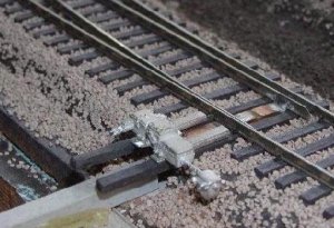
In regard to your question of how to mount the Caboose Industries throw to the turnout, you need to have the throwbar extend out between the headblock ties (not sure of the correct term for these!) and drill ahole to accept the tab on the throw. Spike or glue the throw to the ties. I don't use them since they are so large and look out of place. This photo shows that I use a wire in a piece of plastruct tube, which goes into the throwbar from below. I use slow motion motors (Swichmaster and Tortoise) but a slide switch can be used as well, there are threads here on the gauge which discuss their use. For the photo I placed a Details West (I think) electric switch machine on the ties to show how I intend for it to look someday.
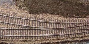
I'm impressed that you were able to build a turnout which works well without a gauge! But use of this one will free you from building to templates. Once you've tried it you'll like it!
Gary
I'm impressed that you were able to build a turnout which works well without a gauge! But use of this one will free you from building to templates. Once you've tried it you'll like it!
Gary
Attachments
Oh, I forgot, you need four gaps, one on each rail coming from the frog. The frog is isolated from all other rail and is fed thru a switch operated by the throw of the turnout, you probably know this. Wire the point/closure rail the same polarity as the adjacent stock rail.
Gary
Gary
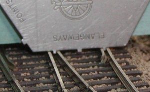
Gap the closure rails between the frog and the last soldered joint before the points. You may want to add another PC board tie to hold the railends. A lot of soldered joints on the points is better.
For electrics, have some PC board connecting the points to the stock rail i.e. don't gap at that point, but do isolate the the frog from the stock rails. Isolate the ties between the points.
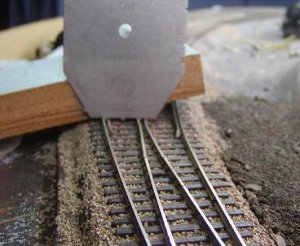
As well as the NMRA gauge, a 3-point track gauge is handy -- it holds the rail while you solder. Get one that matches your rail code.
For electrics, have some PC board connecting the points to the stock rail i.e. don't gap at that point, but do isolate the the frog from the stock rails. Isolate the ties between the points.
As well as the NMRA gauge, a 3-point track gauge is handy -- it holds the rail while you solder. Get one that matches your rail code.
Nice. Look's better than my scratch built ones. All those were good for was the trash on load's for cars. I agree fully with Zedob on those Central Valley kits. I've built three of them and they are better than beautiful. I'm using the CV ties with code 81 rail and details along with Details West frog's and points. These kit's look so real that you can't even tell the difference even when looking at them face to face. You would think a real switch was put in a shrinking machine. No hassle with keeping the rails in gauge while building it because the ties are already gauged. How ever as far as CV kit's they are very easy to build and cost $15.00 and under. For manufactured they rang $15.00 and up. I highly recommend them. I like Proto 87 not for their switch kit's but for the induvidual tie plates which make great load's for gondola's along with their super scale spikes(very tiny) I used their point throw bar's on my CV switchs for every aspect of detail. Here are the link's to Central Vally, Details West, and Proto 87.
http://www.cvmw.com/
http://www.detailswest.com/
http://www.proto:87stores.com/
http://www.cvmw.com/
http://www.detailswest.com/
http://www.proto:87stores.com/