Galileo Shuttlecraft from Star Trek

bgt01

Exemplary Confidant
Jan 26, 2012
576
843
93
Ohio
That's why I also watch bad movies; otherwise you wouldn't know what NOT to do!

Movies and TV also teach us important things like: never go skinny dipping at summer camps where horrible murders take place, never split up - EVER, the homely kid in class is really super hot so date them NOW, always check the back seat of your car, the villain you just killed isn't really dead...but people just keep doing this stuff!;)

Oh, and since this is a Star Trek thread, if you wear a red shirt and get picked for the landing party - DON'T GO!:eek:
 

bgt01

Exemplary Confidant
Jan 26, 2012
576
843
93
Ohio
EXTERIOR

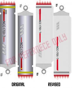
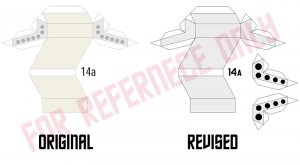
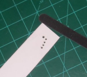
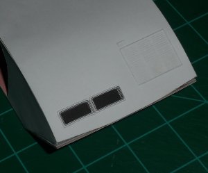
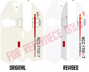
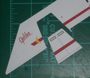
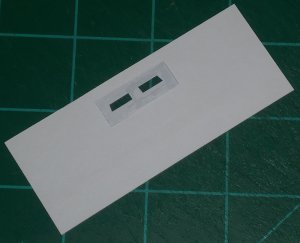
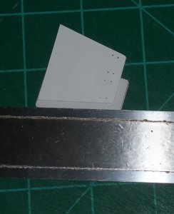
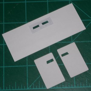
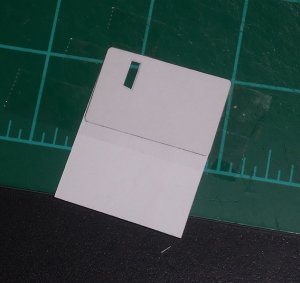
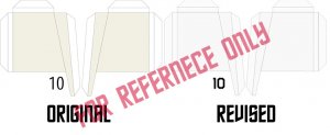
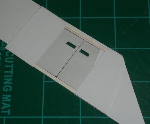
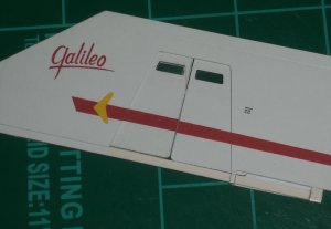
CHANGES MADE: Made new sliding doors to compensate for new hull stripe. Corrected door windows for shape to match studio model. Added “Push” panel by door. Added missing hull markings by door.

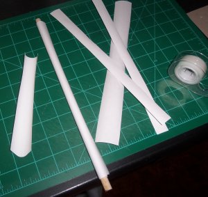
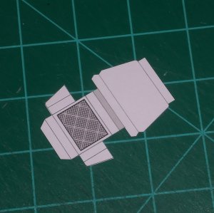
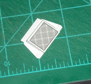
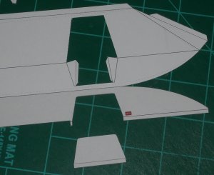
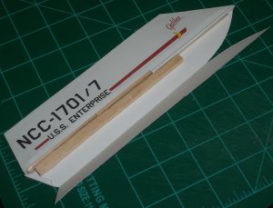
Here’s where things start getting really “seat-of-the-pants” building. The outer sides of the shuttle were designed to be hollow wedge shapes with skinny wings. That wasn’t going to work for me. To make things a little easier on me, I started with the starboard side since it has no door.

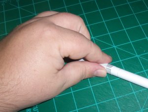
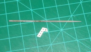
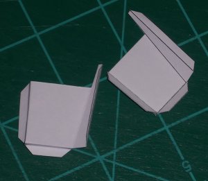
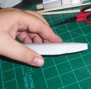
First, I cut off the wings to address separately. That gave me an outer top piece and a outer bottom/inside piece. The inside piece needed to stay flat for gluing to the main body. I took some double-sided tape along the top edge where the inner and outer skin come together and curve. Next, I laid the piece flat and glued the upper forward and rear edges together. That gave me the upper hollow “pocket” of the skin. I glued craft sticks together with Super Glue gel until they made a solid brace across the center line. I cut the sticks at the front and rear to match the angle of the hull. This worked perfectly to keep everything straight.

I needed more sticks to completely fill the hole left by removing the wing, and give the wing something to attach to when I put it back on. I glued four more sticks together and only made them reach about 3/4 from the front to the rear, as the front/lower section starts to come together to a narrow point. Leaving these sticks square caused the center line to be too square and didn’t let the center line come together correctly. I solved this by using my X-acto to shave off, a little at a time, the top stick at an angle that matched the curve of the hull.

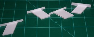
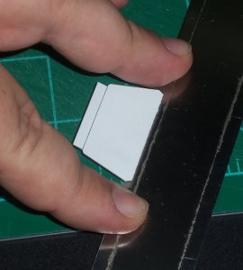
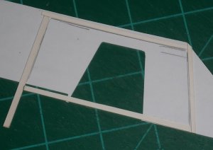
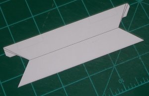
In the old design, the skinny center line you see is supposed to be folded out on the top and bottom and glued together to form a paper-thin lip. This doesn’t match the studio model, which has a thicker, wider center lip. I’m going to address this as a separate issue, but the section as drawn is about the right height of the lip that should be there. When I glued them down I overlapped these sections to use as a guide later.

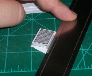
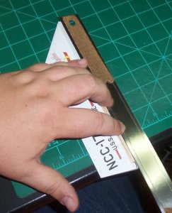
To get a nice, straight, flat center edge I used my ruler to hold down the paper on the craft sticks while gluing.

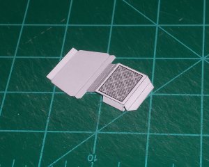
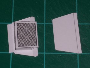
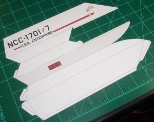
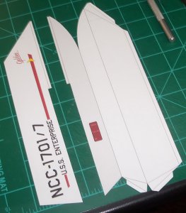
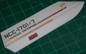
With the edges sealed, the wing hole stuck out like a sore thumb. I covered it up with a piece of scrap hull cut to size and glued in place. Doing it this way created seams that aren’t on the original Galileo because the wings are molded in. But, I’d rather have a few extra seams than crappy wings.

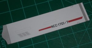
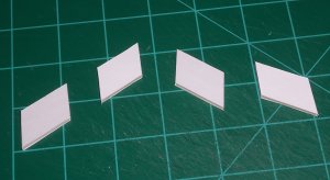
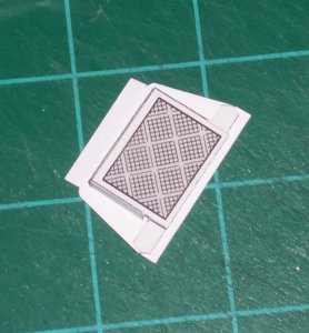
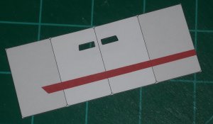
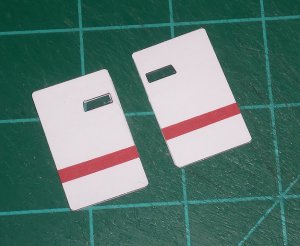
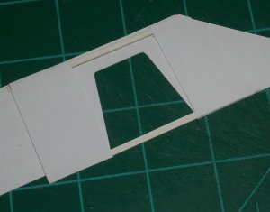
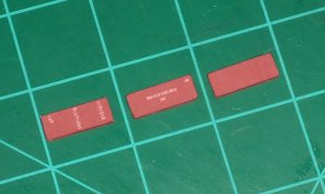
Next, I layered the red panels that go along the bottom of both sides of the hull and attached the starboard one.

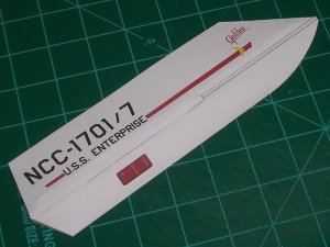
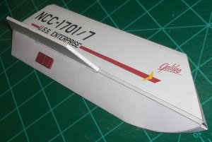
I glued the forward angled piece that covers the hole in the hull in place using Super Glue gel. The widest part of the piece ends right below the center line because of the way I’m building it. That leaves a small hole at the center line which will be covered by whatever new center lip I come up with.
 

Attachments

  • exterior.jpg
    exterior.jpg
    196.4 KB · Views: 28
  • j1.JPG
    j1.JPG
    167.5 KB · Views: 28
  • j2.JPG
    j2.JPG
    150.3 KB · Views: 29
  • j3.JPG
    j3.JPG
    238.3 KB · Views: 29
  • j4.JPG
    j4.JPG
    157 KB · Views: 29
  • j5.JPG
    j5.JPG
    208.6 KB · Views: 30
  • j6.JPG
    j6.JPG
    163.2 KB · Views: 28
  • j7.JPG
    j7.JPG
    117.2 KB · Views: 29
  • j8.JPG
    j8.JPG
    129.2 KB · Views: 29

bgt01

Exemplary Confidant
Jan 26, 2012
576
843
93
Ohio
On the original Galileo, the wings are as thick as the center lip where they flow into the center line and taper slightly out to the flat edges. The original model wings create really skinny wedge shapes that come to a point. For me, the best way to do the wings was to cut the top piece off, glue the bottom to 2mm white picture mounting board I got at Hobby Lobby, and paint the edges white with a paint pen. I glued them in place with Super Glue gel being careful to keep the wing at 90 degrees. They don’t have that slight taper, but they are flat and super strong.

Lastly, I used some rods and tweezers to curl the top section of the hull.
 

Attachments

  • j9.JPG
    j9.JPG
    122 KB · Views: 13
  • j10.JPG
    j10.JPG
    198.4 KB · Views: 16

Revell-Fan

Co-Administrator
Staff member
Administrator
Moderator
Aug 1, 2009
11,595
12,338
228
Vreden
Oh, and since this is a Star Trek thread, if you wear a red shirt and get picked for the landing party - DON'T GO!:eek:

Recently a demonstration took place at Starfleet HQ. People were shouting and holding up plates and banners saying "Red shirts - NO!"
Starfleet HQ acted promptly. All red shirts were withdrawn and destroyed. Now all tech and security officers wear GREEN shirts.

A similar event will take place tomorrow at Stargate SG-1 HQ. All officers participating in an away mission are to be equipped with a first name...

;)
 
  • Like
Reactions: bgt01

Revell-Fan

Co-Administrator
Staff member
Administrator
Moderator
Aug 1, 2009
11,595
12,338
228
Vreden
Sorry @Revell-Fan I couldn't figure out how to make the quote say "Revell-Fan said." How do you do that?
?
What do you mean?

EDIT: Oh, now I got it. Just click "Reply" and write your reply below the quote. The quote ends with [ / QUOTE ], the "... said" text is generated by the quotation "prefix" which looks like [ QUOTE = "bgt01, post: 999129, member: 57545" ]. :) No worries, I know what you were trying to say. :)
 
Last edited:

zathros

*****SENIOR ADMINISTRATOR*****
Staff member
Administrator
Moderator
Apr 5, 2013
13,499
9,551
228
The sliding walls, and double sided walls were quite a pleasant surprise with this model. It is really a great design, especially considering how long it's been around.
 

Tonino

Well-Known Member
Apr 15, 2004
791
1,775
83
61
Republic of San Marino
www.facebook.com
WOW, this is going to be a scratch build rather than a customization! You are going to re-do the whole thing from the beginning. Great work! I'm enjoing this thread a lot!

Do you are a rocket-modeller building at light speed or did you have some photos ready and you are posting them a little at the time to keep our attention?

Thanks @mcusanelli My builds are so slow because ...

Do you think this build is slow? :wideyed:

PS: I absolutely LOVE detailed interiors: this shuttle is coming along a real wonder!!
 
Last edited:
  • Like
Reactions: bgt01

bgt01

Exemplary Confidant
Jan 26, 2012
576
843
93
Ohio
@Revell-Fan Thanks, man. It's always nice when someone figures out what I'm talking about.;) Glad to see someone's being a voice for the Red Shirts.

@zathros It is a nice model and a good design, especially since most of the tweaks it needs are just cosmetic.

@Tonino You caught it!:biggrin: This build is a little deceptive because I did have a good bit built before making posts on this one. The really slow part is me taking 4-5 hours to figure out how I'm going to assemble something (like the walls) because I'm making it up as I go.
 
  • Like
Reactions: Tonino

zathros

*****SENIOR ADMINISTRATOR*****
Staff member
Administrator
Moderator
Apr 5, 2013
13,499
9,551
228
It really is worth putting whatever you do into it, as it is a great model, and you are doing a great job on it. :)
 
  • Like
Reactions: bgt01

bgt01

Exemplary Confidant
Jan 26, 2012
576
843
93
Ohio
ENGINES

CHANGES MADE: Added fold-out step area to port drive engine. Added louvered areas to drive engines.

I hate making tubes!:realmad: 
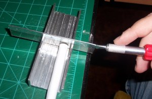
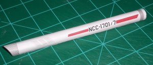
I’m sure I’ve mentioned it before, but it bears repeating. Luckily, or unluckily depending on your outlook, I’ve had lots of practice. These engines are standard nacelles so the only change was the repaint.
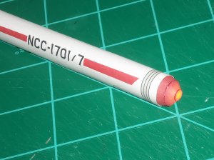
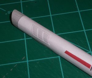
I trimmed everything out and cut off the tabs. I also ditched the “petal” bussard collector. I can’t stand those designs. They are impossible to make look right or good. I also cut off the rear end cap.

Next, I took a straight wood dowel and layered it up with printer paper and double-sided tape until it matched the nacelle dimensions. This gave me nice, straight, solid engines that will better support the model’s weight. I cut the dowel to size using my razor saw and a mitre box. I put a strip of double-sided tape where the seams met up and pushed everything into place, then I went back and put in a little regular gel glue to lock the seam in.

I wanted to find some domed plastic for the bussards but nothing fit. So, I went to my old tried-and-true Rawen bussards from the parts box. The ones I already had printed were the perfect size! I added a round end piece to the engine end for the bussard to glue to and it looks great. Then, I added the louvers at the end. Like before, I made them look more 3-D by scoring the lines. I don’t know yet how I’m going to do the end caps with the domes.
 

Attachments

  • engines.jpg
    engines.jpg
    298.6 KB · Views: 26
  • k1.JPG
    k1.JPG
    364 KB · Views: 26
  • k2.JPG
    k2.JPG
    574.1 KB · Views: 26
  • k3.JPG
    k3.JPG
    376.1 KB · Views: 25
  • k4.JPG
    k4.JPG
    460.9 KB · Views: 27
  • k5.JPG
    k5.JPG
    473.6 KB · Views: 25
  • k6.JPG
    k6.JPG
    329.5 KB · Views: 26
  • k7.JPG
    k7.JPG
    284.6 KB · Views: 25

bgt01

Exemplary Confidant
Jan 26, 2012
576
843
93
Ohio
PYLONS

CHANGES MADE: Took “brace end” art off drive pylons and made end hull gray to match studio model. Set brace end art off by itself to make braces stand alone pieces.

The original design for this part is a simple box, which does not match the studio model at all. The L-shaped parts with holes are braces that attach to the inside of the pylons. I wanted these to be sturdy, so I glued the flat part to 2mm white backer board. I used my metal pick to mark the edges of the part for cutting. Before trimming, I drilled out the holes using my pin vise. Working with part glued as a bigger piece made the drilling easier. I cleaned and smoothed the holes using smaller drill bits and my round file, then did the final trimming. I cleaned those edges with a flat file.

The backer board is just layers of pressed paper, so trimming it that small made the layers start to separate. To keep everything together I put some Brush-on Super Glue on the edges. Because the interior layers of the backer board are yellowish I painted the edges with a white paint pen. These parts should actually be gray all the way around and the flat sides are, but my gray Sharpie was way too dark so white was the next best choice. Those edges are hard to see anyway so the color shift isn’t in your face.

The flat pylons were made in the same fashion, except for the edges. I wanted them to match in color so I glued strips of scrap gray to the edges and trimmed them to size with my precision scissors.
 

Attachments

  • new pylon.jpg
    new pylon.jpg
    123.4 KB · Views: 17
  • l1.JPG
    l1.JPG
    816.9 KB · Views: 15
  • l2.JPG
    l2.JPG
    286 KB · Views: 13
  • l3.JPG
    l3.JPG
    321.8 KB · Views: 13
  • l4.JPG
    l4.JPG
    673.2 KB · Views: 13
  • l5.JPG
    l5.JPG
    414.9 KB · Views: 13
  • l6.JPG
    l6.JPG
    466 KB · Views: 13

bgt01

Exemplary Confidant
Jan 26, 2012
576
843
93
Ohio
MORE ASSEMBLY

The main body has been assembled for awhile, so I went back and added the raised detail for the two ducts on the lower port side of the forward hull. These ducts go farther back into the actual Galileo, but I didn’t want to get into creating an inner assembly just to have “deeper black” areas that aren’t critical to the look of the model.
 

Attachments

  • m1.JPG
    m1.JPG
    410 KB · Views: 10

bgt01

Exemplary Confidant
Jan 26, 2012
576
843
93
Ohio
DOOR STEP

The door step has several mountain and valley folds. It basically forms a box on the back of the lower door section. I used my metal ruler to hold sections straight and flat while the glue set up. This kept any ugly ripples from forming on the outer hull section.

This whole section was then glued to the section of door cut from the hull. I used a light coat of Gel Glue spread with a toothpick and set the bottle of glue on the part while drying to keep it flat and avoid ripples in the skin.
 

Attachments

  • n1.JPG
    n1.JPG
    340.3 KB · Views: 11
  • n2.JPG
    n2.JPG
    466.8 KB · Views: 12
  • n3.JPG
    n3.JPG
    445.8 KB · Views: 11
  • n4.JPG
    n4.JPG
    350.8 KB · Views: 11
  • n5.JPG
    n5.JPG
    361.9 KB · Views: 11
  • n6.JPG
    n6.JPG
    232.2 KB · Views: 10
  • n7.JPG
    n7.JPG
    257.7 KB · Views: 10

bgt01

Exemplary Confidant
Jan 26, 2012
576
843
93
Ohio
DOORS

CHANGES MADE: Changed shape of door windows to match studio model. Redid style and placement of pennant across door seams to match.

I carefully cut the door sections out of the hull. Then, I cut the windows out of the actual square sliding doors. I glued a piece of acetate to the back for window glass and let it dry thoroughly. I took the cut out doors and used my metal pick to poke holes in all four corners of each window. I then used this as a template for cutting out the back of the door skin for the windows. I used a thin coat of Gel Glue to glue one skin on and placed a heavy bottle on it to keep it flat while drying. Then I remembered how I wanted to do it and used double-sided tape to attach the second door skin. That worked better. Finally, I trimmed the doors to size.
 

Attachments

  • exterior.jpg
    exterior.jpg
    196.4 KB · Views: 19
  • o1.JPG
    o1.JPG
    494.1 KB · Views: 19
  • o2.JPG
    o2.JPG
    431.2 KB · Views: 18
  • o3.JPG
    o3.JPG
    294.7 KB · Views: 18
  • o4.JPG
    o4.JPG
    350.8 KB · Views: 18
  • o5.JPG
    o5.JPG
    293.2 KB · Views: 19
  • o6.JPG
    o6.JPG
    347 KB · Views: 18
  • o7.JPG
    o7.JPG
    240.5 KB · Views: 18
  • o8.JPG
    o8.JPG
    301.5 KB · Views: 19

bgt01

Exemplary Confidant
Jan 26, 2012
576
843
93
Ohio
The original door pockets are a box-like design that left the doors sitting more loose that I wanted. And, I wanted to make sure the pennant lined up on the doors and the hull correctly. So, I decided to scratch build a new door holder.

First, I laid the doors on the inside of the hull and marked their open positions. I found the forward door couldn’t be opened all the way unless it had one side trimmed at an angle to match the hull. Then I cut strips of 1mm white board and framed out the door section. This is just slightly thicker than the doors, so they fit much tighter to the hull. Because of the way I’m building it the bottom strip lines up with the centerline.

With the frame glued in, I cut pieces of white card to skin the back and hold the doors in. I slid the doors in and tested the fit and found I’d left a little too much gap at the top between the doors and the frame. I glued a very small sliver of card in to tighten it all up.

I’m leaving the bottom card section across the door until I get closer to sealing the hull up. I also cut off the little tabs the original door design had for opening and closing. My current plan is to attach two small magnets to the inside and use them for opening. If that doesn’t work, I will probably just put a small hole in each door at the strip and use my pick to open and close them. Either way it’ll look cleaner than those tabs do. There’s probably more I’ll have to address as I go with this new design.
 

Attachments

  • doors1.jpg
    doors1.jpg
    58.9 KB · Views: 15
  • o9.JPG
    o9.JPG
    248.9 KB · Views: 14
  • o10.JPG
    o10.JPG
    259 KB · Views: 13
  • o11.JPG
    o11.JPG
    409.7 KB · Views: 14
  • o12.JPG
    o12.JPG
    448 KB · Views: 15
  • o13.JPG
    o13.JPG
    291.7 KB · Views: 15