USS Cairo Test Build

fishBait

Member
Mar 15, 2012
117
0
16
modelsnmoore.com
The test build has started and pictures here will follow the build. Three errors in the prototype sheets have been caught (one
a major fix) and corrected.

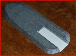
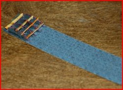
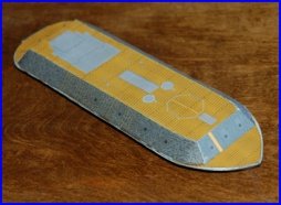
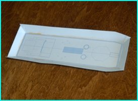
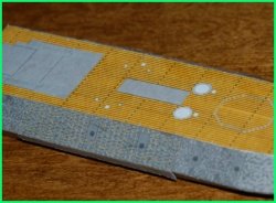
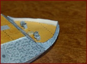
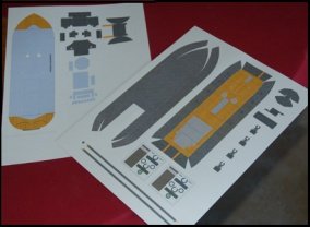
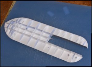
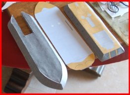
1) View of a couple of the prototype parts sheets.
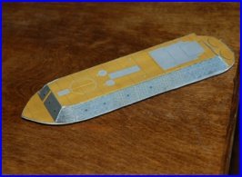
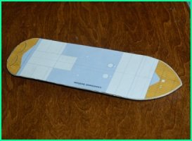
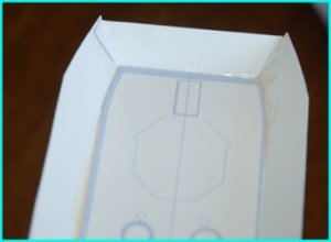
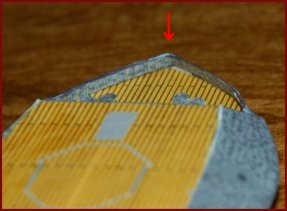
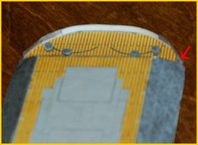
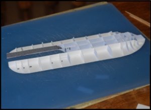
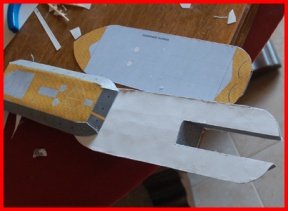
2) Shot of the hull top with formers installed.
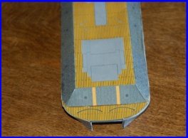
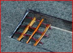
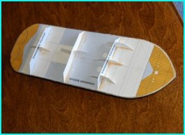
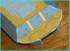
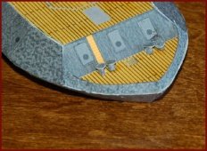
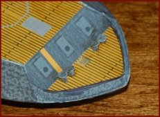
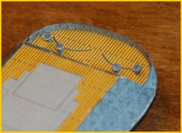
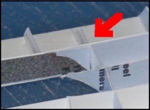
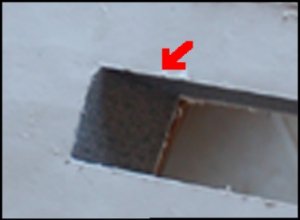
3) Closeup shot of the hull top and formers showing the wheel well braces installed.
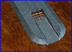
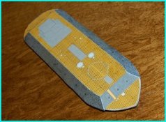
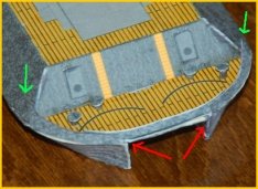
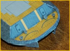
4) Same shot as #3 showing side wheel well brace installed on one of the side keels.

fishBait
 

Attachments

  • p01.jpg
    p01.jpg
    23.4 KB · Views: 24
  • p02.jpg
    p02.jpg
    22.1 KB · Views: 16
  • p03.jpg
    p03.jpg
    22.1 KB · Views: 23
  • p04.jpg
    p04.jpg
    22 KB · Views: 17
Z

Zathros

It looks like it's going to be a nice model. A representation from that era that was real!!

asfefergf_1.jpg


As she rests today:

IMG_3780.JPG
 

fishBait

Member
Mar 15, 2012
117
0
16
modelsnmoore.com
Continuing the build. I will keep the graphics numbers in order for future reference.
5) Completed hull, the main deck just cut from the parts sheet, and the casement assembled with formers.
6) Same as #5, but from a different angle to show the wheel well on the hull.
7) Closeup of #6 showing the wheel well cover installed on the formers (see #3).
Tomorrow, hopefully, we will be installing the casement on the hull and setting the stage for adding upper details.
fishBait
 

Attachments

  • p05.jpg
    p05.jpg
    24 KB · Views: 23
  • p06.jpg
    p06.jpg
    22.4 KB · Views: 18
  • p07.jpg
    p07.jpg
    19.9 KB · Views: 17

fishBait

Member
Mar 15, 2012
117
0
16
modelsnmoore.com
It looks like it's going to be a nice model. A representation from that era that was real!!

asfefergf_1.jpg


As she rests today:

IMG_3780.JPG
Thanks Zathros. I have really enjoyed the design and now the building. I have wanted a USS Cairo ever since I visited Vicksburg right after they raised her. They were just getting the keel and hull laid down.

Nest is the USS Benton and USS Essex followed by the USS Deleware.

fishBait
 
Z

Zathros

You do great service to the collective memory of our country by preserving these ships in model form, and by offering them for FREE, you keep it accessible to everyone. That is awesome! :)
 

fishBait

Member
Mar 15, 2012
117
0
16
modelsnmoore.com
Now install the paddlewheel and casement on the hull. The first step is simply gluing the Casement Bottom (main deck) on top of the hull. Watch the alignment here. Alignment is more critical at the stern at this point. If it is too short at the bow, no problem. If it is too long, it can be
trimmed later. Just make sure the stern is in allignment.
Yes Virginia, there should be a photo of the hull with the main deck mounted on it. That is one that got away from us.
8) The USS Cairo should now look like this from the bottom, the white underside of the main deck clearly
visible.
9) Cut a strip equal to gap width between the hulls and longer than the gap. Assemble the paddlewheel on the strip 1/8 inch back from one end.
10) Slide the strip with the paddlewheel into the gap area and properly align it. Mark the main deck stern on the strip; remove and trim to length. Apply glue to the main deck undersides in the gap; reinsert the strip and paddlewheel; align carefully and press down to make a good glue joint.
11) The USS Cairo should now look like this from the pottom.
Continued,
fishBait
 

Attachments

  • p08.jpg
    p08.jpg
    22.9 KB · Views: 15
  • p09.jpg
    p09.jpg
    23.2 KB · Views: 19
  • p10.jpg
    p10.jpg
    25.1 KB · Views: 18
  • p11.jpg
    p11.jpg
    23.7 KB · Views: 16

fishBait

Member
Mar 15, 2012
117
0
16
modelsnmoore.com
12) Test fit the casement on the hull. Fit should be good, but you may have to do a little trimming here. Critical alignment is at the forward end of the casement. When the fit is good, glue the casement to the hull.
13) Another view.
14) and one more.
The Cairo is starting to resemble a Pook Turtle. Next we start adding top side detail. But that is another story.

fishBait
 

Attachments

  • p12.jpg
    p12.jpg
    22.9 KB · Views: 16
  • p13.jpg
    p13.jpg
    22.1 KB · Views: 16
  • p14.jpg
    p14.jpg
    22.9 KB · Views: 18

fishBait

Member
Mar 15, 2012
117
0
16
modelsnmoore.com
After the last post, a serious design flaw was discovered while preparing this post. Some redesign was necessary, and the last two posts must be replaced and the work redone.

Restart at Step #8, mentally delete the previous steps 8-14. Here are the new steps 8-14:

We will now install the paddlewheel and casement on the hull. The first step is simply gluing the Casement Bottom (main deck) on top of the hull. Watch the alignment here. Alignment is more critical at the stern at this point. If it is too short at the bow, no problem. If it is too long, it can be trimmed later. Just make sure the stern is in alignment.
8) Main deck installed on the hull.
9) The USS Cairo should now look like this from the bottom, the white underside of the main deck clearly visible.
10) Cut a strip equal to gap width between the hulls and longer than the gap. Assemble the paddlewheel on the strip 1/8 inch back from one end.
11) Slide the strip with the paddlewheel into the gap area and properly align it. Mark the main deck stern on the strip; remove and trim to length. Apply glue to the main deck undersides in the gap; reinsert the strip and paddlewheel; align carefully and press down to make a good glue joint.
12) The USS Cairo should now look like this from the bottom.
13) Cut out and assemble the casement. Assembly is straight forward, but has has two unique aspects. First, there are two stiffners glued to the inside top of the casement for strength. Second, the four corners do not meet perfectly, but are offset (see next graphic).

More follows,

fishBait
 

Attachments

  • p08.jpg
    p08.jpg
    22.9 KB · Views: 15
  • p09.jpg
    p09.jpg
    22.9 KB · Views: 16
  • p10.jpg
    p10.jpg
    23.2 KB · Views: 15
  • p11.jpg
    p11.jpg
    25.1 KB · Views: 13
  • p12.jpg
    p12.jpg
    23.7 KB · Views: 15
  • p13.jpg
    p13.jpg
    22.2 KB · Views: 15

fishBait

Member
Mar 15, 2012
117
0
16
modelsnmoore.com
14) Closeup of one end of the casement underside. The offsets at the corners are correct.
15) Cut out the casement formers and mount them on top of the main deck. I used scrap paper to make them double thickness and added scrap paper re-enforcement.
16) Test fit the casement over the casement formers and main deck. The bow and stern armor should meet the main deck at the light gray join lines. The side armor should fit down and around the main deck meeting the hull armor in the classic Pook Turtle fashon (see graphic). If necessary, trim the casement formers to avoid distorting the casement. Glue the casement to the main deck and formers.
17} Another view showing the casement fit and overlap.
18} Examining the photo of the actual USS Cairo, the sharp demarcation line between the heavy armor and lighter armor on the sides is clearly evident.
19} Trim the casement overlap around the joint with the hull making a smooth transistion. Cut out, bend and glue the heavy side armor on each side. Be careful of the alignment. Notice the glue joint on the bottom of the heavy armor has sprung loose. I pushed the drying time to get the post on tonight. Don't worry, I fixed it.

More follows,

fishBait
 

Attachments

  • p14.jpg
    p14.jpg
    20 KB · Views: 16
  • p15.jpg
    p15.jpg
    23.1 KB · Views: 12
  • p16.jpg
    p16.jpg
    22.9 KB · Views: 14
  • p17.jpg
    p17.jpg
    24.6 KB · Views: 16
  • p18.jpg
    p18.jpg
    23.4 KB · Views: 12
  • p19.jpg
    p19.jpg
    22.7 KB · Views: 13

Rhaven Blaack

!!!THE MAN BEHIND THE CURTAIN!!!
Staff member
Administrator
Moderator
Jun 12, 2009
12,493
9,857
228
Oregon
www.deviantart.com
You are doing a really good job in designing this model. I like how you are chronicling your steps carefully throughout your build.
I also like fact that you are putting formers throughout the model.
It looks lie it will be a fun build.
keep up the great work.
 

fishBait

Member
Mar 15, 2012
117
0
16
modelsnmoore.com
You are doing a really good job in designing this model. I like how you are chronicling your steps carefully throughout your build.
I also like fact that you are putting formers throughout the model.
It looks lie it will be a fun build.
keep up the great work.

Thanks for the kind words. Will try to keep it going in the same manner.

fishBait
 

fishBait

Member
Mar 15, 2012
117
0
16
modelsnmoore.com
23) If the optional add on gun port covers are desired, cut them out and glue them on over the preprinted locations. Now we will also insall the forward gunnels. This is a fairly difficult procedure. Pick one side of the Cairo and cut out the forward gunnel for that side. Test fit and make sure that the angle between the casement and gunnel is correct; if not adjust and test fit again until you have a good fit. TRIMMING IS A NECESSITY! Glue the gunnel on with a butt joint to the bow armor and a short run on the main deck.

24) Now glue the gunnel on around to the apex of the bow. The gunnel should transition from the angle at the bow armor to perpendicular or near perpendicular to the main deck at the bow apex. Let dry throughly before attempting the other side. Repeat on the other side of the Cairo and join the two gunnels at the bow. Again, allow to dry throughly. At this point, we have another decision to make. The inside of the gunnels are glaringing white.

25} If desired, install the three piece interior gunnel wall. Cut out both interior side gunnel walls. Again, trim to fit your Cairo at the joint with the bow armor. Allow to dry until stable! Cut out the third interior gunnel wall piece, the apex. Fold in the center and crease, printed side in. Apply glue and use a toothpick to press the crease into the bow gunnel apex (red arrow). Then make sure that each side attaches to the interior gunnel wall while making sure that the apex is secure.

26} The USS Cairo forward deck is now complete.

Stay tuned to this station. Next, we will give the same treatment to the stern area.
 

Attachments

  • p23.jpg
    p23.jpg
    23.3 KB · Views: 14
  • p24.jpg
    p24.jpg
    23.2 KB · Views: 17
  • p25.jpg
    p25.jpg
    22.7 KB · Views: 15
  • p26.jpg
    p26.jpg
    23.7 KB · Views: 17
Z

Zathros

Very nice! I too am impressed with the formers in what must be a very rigid hull. :)
 

vbsargent

Member
Apr 16, 2008
175
3
16
MD, USA
I have to admit that I'm not particularly interested in ironclads, but this one has piqued my interest. I like the treatment you are giving to the Cairo. The graphics are nice and clean, the assembly seems a good blend of simple cut & paste with elements of scratch building. Could serve as a good introduction to more advanced methods used in paper modeling.
 

fishBait

Member
Mar 15, 2012
117
0
16
modelsnmoore.com
Very nice! I too am impressed with the formers in what must be a very rigid hull. :)

I agree, the hull and casement together is as rigid as any plastic model I have built. Very strong. I am considering using the technique on future HO models to handle the track and train weight.

fishBait
 

fishBait

Member
Mar 15, 2012
117
0
16
modelsnmoore.com
I have to admit that I'm not particularly interested in ironclads, but this one has piqued my interest. I like the treatment you are giving to the Cairo. The graphics are nice and clean, the assembly seems a good blend of simple cut & paste with elements of scratch building. Could serve as a good introduction to more advanced methods used in paper modeling.

Thank you for your kind words. I would add two comments to your observations. 1) This is my first design of a papermodel, but even if it were not, should not the test build of any new model design be considered scratch building? 2) Tabs I do not mind, that is tabs that fold and attach to the opposing part. Slits I do not like at all and have trouble cutting them and/or using them without introducing some part distortion. I went out of my way and spent time to design the Cairo with NO SLITS! I feel that this will attract new papermodelers to the hobby if more are designed in this way. I hope it will become a recognizable feature of my designs.

I hope that my comments do not disturb you or others. I felt I saw some of my ideas and feelings in your statement.

Thanks,

fishBait
 

fishBait

Member
Mar 15, 2012
117
0
16
modelsnmoore.com
27) The gun doors and rudder cable rollers (same as deck cleats on the bow deck) have been installed on the aft deck. We will use a different technique to install the gunnels. The side gunnels only go around to the end of the main deck splashboard (red arrow). Test fit and trim the gunnels as before. Position the gunnel (one side at a time) and glue to the main deck/hull all the way around, but do not glue the angle to casement butt joint (blue arrow). As soon as these are stable, glue the third piece around the stern. Allow to dry thoroughly.

28) Gently transition the gunnel upsweeps to fair into the stern armor (red arrow) and glue. Allow to dry thoroughly. Again, the interior wall of the gunnel is glaringly white.

29) Cut out the interior gunnel wall. It should fit from just inside the armor-gunnel joint all the way around to the opposing armor-gunnel joint. Test fit and trim. Glue the interior gunnel wall into place. This new technique is vastly superior and will be used in the future to install the bow gunnels.

30} With the exception of rudders and control cables, the USS Cairo's aft main deck is now complete.

For the next post, we move up to the hurricane deck and start installing the USS Cairo's most recognized identifying features.

fishBait
 

Attachments

  • p27.jpg
    p27.jpg
    24.8 KB · Views: 12
  • p28.jpg
    p28.jpg
    22.4 KB · Views: 14
  • p29.jpg
    p29.jpg
    23.2 KB · Views: 15
  • p30.jpg
    p30.jpg
    25.1 KB · Views: 20
Z

Zathros

I agree, the hull and casement together is as rigid as any plastic model I have built. Very strong. I am considering using the technique on future HO models to handle the track and train weight.

fishBait

It will also add to the longevity. I had a discussion with a designer who was enraged when I pointed out a problem with his model. Sometimes people ask for suggestions, but don't really want them. This person destroyed their model, blaming me. :cry:

I thought to myself, first, it was a prototype. Second, the whole model could have printed on the thinnest weight paper, and that laminated over the hull, and there would be nothing noticeable.

I learned from one member an excellent method for hiding corner seams by using folded piece of paper, cut along panels lines. Since this person really details his models, I could not see a paper model, but I did see a spaceship, the Rodger Young.

I designed a model a long time ago. I never released it because the nose section is extremely complicated. I have come to the conclusion that it will have to be built, and since few people like to paint their models, and want them printed, this model will need a "skin" with the graphics, to make a presentable model.

I like your model. I like your build technique. I like the website you have started and I really like the premise and philosophy behind what you are doing. I think it's great!! You get my support and endorsement, for whatever that's worth. :thumb:

(sorry for the long ramble)


.
 

fishBait

Member
Mar 15, 2012
117
0
16
modelsnmoore.com
A-HAH, do I detect a fellow Robert Heinlein fan. Only man I know that conceived of a space ship called the Roger Young! One of the best SF writers ever.

Thanks for your kind words. Don't ever hesitate to present suggestions to me. That is how we learn. I am filing your paper skin concept for future use, it is a great scheme. And I think it is worth a lot!

Thanks again,

fishBait
 

vbsargent

Member
Apr 16, 2008
175
3
16
MD, USA
I have trouble imagining a model utilizing slots and tabs. I used to design corrugated (cardboard) displays, you know, the ones you see in the supermarket. WE used slot and tabs for just about everything, because it was cheaper than glue and the display always had to be shipped flat and assembled by the supermarket. But we always ALWAYS accounted for the thickness of the cardboard. Even after twenty years I remember B fluted cardboard is 1/8" and C is 3/16". If one doesn't cut the slit in the card as a bracket (accounting for the thickness of the card) one cannot avoid getting distortion.

Starship Troopers is a seminal work by Heinlein, but I have to admit that I think that I like "The Cat Who Walks Through Walls" just a bit better.