

Model Of The Month: 1/4 Scale Mercury Capsule: Done 1/1 Scale
- Thread starter PaperAir
- Start date
You are using an out of date browser. It may not display this or other websites correctly.
You should upgrade or use an alternative browser.
You should upgrade or use an alternative browser.


Oh my god... it just looks fantastic.
Wouldn´t be surprised if it´ll be fully functional in the end :mrgreen:.
Any plans for an Atlas or Redstone rocket afterwards?
Wouldn´t be surprised if it´ll be fully functional in the end :mrgreen:.
Any plans for an Atlas or Redstone rocket afterwards?
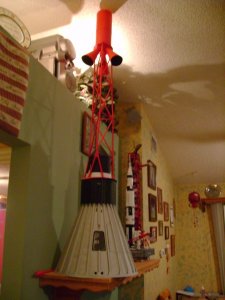
Nice pics there Paul. I'm getting the itch to build the heat sheild and thruster pack but want to hold off to detail the inside. I already have the aft bulkhead and instument pannel laying around. With the LES on top it's touching the ceiling, without the rod on top it's laying on the shelf next to it, so either the LES or the thruster pack would have to be stored elsewhere.
When I get the shingles from Scott I think I will go ahead with the HS and TS and set the LES aside until ready to display. I've been searching for an Astronaut figure for it, it should be 181/2" tall but all I've come up with is the Mercury GI Joe but it's 1/6 scale at 12" inches tall.
When I get the shingles from Scott I think I will go ahead with the HS and TS and set the LES aside until ready to display. I've been searching for an Astronaut figure for it, it should be 181/2" tall but all I've come up with is the Mercury GI Joe but it's 1/6 scale at 12" inches tall.
Attachments
Thank you sir and no rocket.Maybe a1/4 scale GeminiOh my god... it just looks fantastic.
Wouldn´t be surprised if it´ll be fully functional in the end :mrgreen:.
Any plans for an Atlas or Redstone rocket afterwards?


Comming together
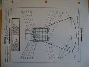
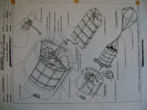
Question....the parachute trays look shallow. In the photos of them in the McDonald Merc manual it shows the trays are at the very bottom of the recovery section, in the frame work that actually extends into the main structure where the hatch attaches.
Did I see this wrong?
Question....the parachute trays look shallow. In the photos of them in the McDonald Merc manual it shows the trays are at the very bottom of the recovery section, in the frame work that actually extends into the main structure where the hatch attaches.
Did I see this wrong?
Attachments

.JPG")
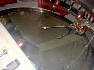
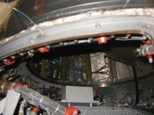
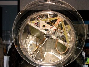
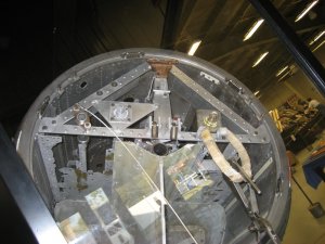
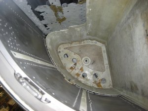
The drawing you posted gets it right. The container is deeper than you built. The photo you show is deceiving. The lower part of the container overlaps the divider walls by less than an inch. Here are some more photos. Hope they help. A few are from Mike at heroicrelics.org and a few are taken by me. I don't show the container on my cross section (on the plans page) but the container goes to just above the forward hatch bulkhead. You can clearly see this in the photos of SN7 which is missing the hatch.
It also looks like your container is glued in. Remember it slides out. This was the primary means of egress. There are photos posted earlier.
The first two are Freedom (SN7, the middle one is same as you show, Sigma (16) and the last two are Liberty Bell (11). Don't get wrapped up looking at the structure detail on 11. It was coroded away and they just added some simple structure to hold the parts in place and look good. It does show good views of the parachute container.
Scott
Attachments
Hey Paul
This is the only thing I can think of..it being different between capsules. The one photo you posted is from Phil Smith's resin build, I've been using his pics as reference but I have found some things different with his build and the manual, even the couches used, every capsule is different. I have a guy that can make the couch with his modeling program but he needs six sided photos of it, so far I haven't been able to find pics of all six sides front, back, top, bottom, side to side.
This is the only thing I can think of..it being different between capsules. The one photo you posted is from Phil Smith's resin build, I've been using his pics as reference but I have found some things different with his build and the manual, even the couches used, every capsule is different. I have a guy that can make the couch with his modeling program but he needs six sided photos of it, so far I haven't been able to find pics of all six sides front, back, top, bottom, side to side.
Remember, it just slides in. I haven't looked that close to the position of the container in Sigma 7 but I will now. Its very possible its just slid up a little making it look as such. You can leave yours like it is, I'm just trying to clarify the design/intent.
I'll dig through some photos and add a gallery page to my site. I'll let you know when I get it done.
Scott
I'll dig through some photos and add a gallery page to my site. I'll let you know when I get it done.
Scott


