Bill and Tom's EXCELLENT ADVENTURE in Logging and Mining

Bill Nelson

Well-Known Member
Dec 14, 2008
2,680
467
78
Clarksville Tn
People convert churches to garages there too eh?

! :thumb:


Eric like most Clarksvillains, ain't from around here , He landed here through the U.S. Army. like about half or more the people in Clarksville Have. the Church was in his hometown, out in the Midwest I think. I'll leave the details to Eric, cause I'd screw it up.

Bill Nelson
 

ed101

New Member
Jun 18, 2009
5
0
1
Clarksville, Tn.
Yep! I'm a Midwestern boy! I grew up in Kansas in a town of 2500. the church was about a block from where I lived and we played in the back where all the old cars were left to rust away. In the back right along the fence line was a old school bus that we used as our "fort" it was an old '50's era type and was pretty small and beat up by the time it wound up there. The building, I do believe, did burn down probably due to neglect and the overwhelming amount of combustibles that saturated every part of the lot and building. I've still got to put the shingles on and detail it but it's been fun to remember the times playing in the old cars there.
 

Doctor G

Well-Known Member
Sep 1, 2008
1,415
298
78
Clarksville, Tennessee
More of Eric's imaginative modeling

Here is another of Eric's fine modeling projects on the club layout. Eric can tell you he also saw this repair facility in "real life."

Check out the board by board construction of the wooden deck. Very much a labor of love!!!

Speaking of labor, sorry I missed last PM's RR club. I was at the museum up to my elbows in white glue trying to finish the Thomas the Tank Engine model for display and could not get away for the mess we made.

I will try for this upcoming week.
Doc Tom:eek:ops:
 

Attachments

  • RR CLUB - 80.jpg
    RR CLUB - 80.jpg
    158.4 KB · Views: 27
  • RR CLUB - 81.jpg
    RR CLUB - 81.jpg
    160.1 KB · Views: 22
  • RR CLUB - 82.jpg
    RR CLUB - 82.jpg
    171.6 KB · Views: 24

Hoorhaylowe

New Member
Feb 4, 2008
19
0
1
Dexter, Michigan
Can't Wait Any Longer

Beautiful wood decking, and hey Bill I've been waiting patiently for pics of the track laying...i've started some handlaid myself, but have been waiting for about a month(that's how long you've been threatening to show some pics) to see your work. Oh well I'll just have to be strong and quit whining like one of my kids when I tell them " It's Gonna Take Awhile":mrgreen:. I'm interested in the way in which you lay your switches. I assume you don't use pc ties, but all wood.?
 

Bill Nelson

Well-Known Member
Dec 14, 2008
2,680
467
78
Clarksville Tn
I meant to take my camera. Gr Tom brought his camera to the operating session, but I don't know if he took picls of the ties going in.

I use wood ties for the switch. I often set little pieces of rail, that I have tinned with solder, between the ties @ the frog and wing rails, so that I can solder the whole frog together, and get a stronger assembly. I use PC board as a throw bar. I will have to do some experimenting with my normal proceedure, as my normal design is probably not DCC friendly. I think that won't be much trouble, I will just have to incorporate some of the design features I use with stub switches into a point switch. the main thing needed is to separate the points from each other electrically, so that each point is permanently wedded electrically to it's own stock rail, to prevent a wheel touching both and causing a micro short, which a DC system ignores but DCC can't. I already do something similar with stub switches, as the two rails on the diverging routes are right next to each other at the stub (I have made up my own terminology for stub switches, since I taught myself how to make them).

I will try to get photos of putting the ties down for the last two switches, as tie placement is critical. the rails have to follow the ties, so if you place the ties wrong, good results are highly improbable. I'm making #6 switches. I used an Atlas #6 switch to mark the location of the ties, and the rails at each end.


Before I spike the first rail I'll have the camera there, and document every step- perhaps I ought to start a separate thread on switch building.


Sorry for the delay, handlaying track takes time especially at the club where I have one or maybe two work sessions a week

Bill Nelson
 

Doctor G

Well-Known Member
Sep 1, 2008
1,415
298
78
Clarksville, Tennessee
I meant to take my camera. Gr Tom brought his camera to the operating session, but I don't know if he took picls of the ties going in.


Bill Nelson
Hey Bill,
Yes, I did get some pictures of the track laying going on.....unfortunately there was too much blur to make them useful. Seems there was a nearby working crew sawing and hammering and inducing a jiggle in the camera placed on roadbed technique I like so much.

Be glad to help with photo documentation if you like at future work sessions.

Tom
 

Bill Nelson

Well-Known Member
Dec 14, 2008
2,680
467
78
Clarksville Tn
Hey Bill,
Yes, I did get some pictures of the track laying going on.....unfortunately there was too much blur to make them useful. Seems there was a nearby working crew sawing and hammering and inducing a jiggle in the camera placed on roadbed technique I like so much.

Be glad to help with photo documentation if you like at future work sessions.

Tom


Last night I giggled a lot of that ballast out of position as well, and I had to sweep it back into place. Once I get the rest of the ties down I'll have to get it all into place and mist it and glue it all down before I start playing with rail.

Bill Nelson
 

Doctor G

Well-Known Member
Sep 1, 2008
1,415
298
78
Clarksville, Tennessee
Look out Diesel in the House

I really liked the following shot of Dave Straka's L&N Diesel from the recent operating session. It reminds me of company photographs and calendars from times past.
Doc Tom:cool:
 

Attachments

  • RR CLUB - 85.jpg
    RR CLUB - 85.jpg
    134.8 KB · Views: 5

Hoorhaylowe

New Member
Feb 4, 2008
19
0
1
Dexter, Michigan
Bill thanks for the reply, but there is no apology necessary, I know it takes a long time to properly prepare before starting the handlaying process. It has taken me since the decision to handlay track....oh about a year to start. Thanks for considering to document the process as I have yet to find a thread here that has! Doc great photos and modeling in general it has helped me and a lot of people I'm sure take better pictures and see the detail of their modeling from a whole different perspective! Needless to say it will make us all better modelers.
 

Bill Nelson

Well-Known Member
Dec 14, 2008
2,680
467
78
Clarksville Tn
The important thing about using photographs is not seeing what went right, it is seeing what looks wrong. Looking at something I just built, and trying to see defects is largely useless , like trying to proof read something you just wrote. You'll have better luck catching mistakes if your proof read it later, best to have someone else do it.

photographing your work gives you some of that separation, and lets you see stuff your brain doesn't pick up from you eyes, as your brain knows what it should look like, and can edit out stuff that doesn't fit. For some reason, when we go to a photo of that same scene, that editing process is short circuited, letting us see the flaws, which we can then work to reduce or eliminate.

Bill Nelson
 

Doctor G

Well-Known Member
Sep 1, 2008
1,415
298
78
Clarksville, Tennessee
A Diesel for the narrow guage

We do have a narrow guage section of this club RR that is very interesting. Bill will be converting this little diesel switcher to run on the narrow guage.
Doc Tom:eek:ops:
 

Attachments

  • RR CLUB - 87.jpg
    RR CLUB - 87.jpg
    198.6 KB · Views: 6
  • RR CLUB - 88.jpg
    RR CLUB - 88.jpg
    209.6 KB · Views: 7

Bill Nelson

Well-Known Member
Dec 14, 2008
2,680
467
78
Clarksville Tn
before the handlaying track tutorials

I took my camera to the club tonight t document some of the track laying techniques. before I get to the tie laying pictures, here are some photos of some of my other projects.

here is a picture of the J.E. Patterson Coal and Lumber Co Altimont mine with it's switch engine. also I have a picture of the J.E. Patterson Cumberland #1 mine, which is in Patterson, and is accessed from a switch in the sawmill complex.

I also have a photo of the massive Eismann Copper Co.; which I kitbashed from two old AHM old time factory kits, which I combined to double the height, and two old time brewery kits which I combined to double the length. there is also a photo of the lettering on one of the smokestacks, done with my reverse masking technique.

Bill Nelson
 

Attachments

  • SML Altimont Mine.jpg
    SML Altimont Mine.jpg
    153.6 KB · Views: 4
  • SML  smokestack lettering.jpg
    SML smokestack lettering.jpg
    25.4 KB · Views: 6
  • SML cmbrd #1.jpg
    SML cmbrd #1.jpg
    189.5 KB · Views: 6
  • SML Esm cpr .jpg
    SML Esm cpr .jpg
    150.6 KB · Views: 4

Bill Nelson

Well-Known Member
Dec 14, 2008
2,680
467
78
Clarksville Tn
SML ctng ts.jpg SML gl T #1.jpg SML gl T #2.jpg SML gl T ##3.jpg SML blsting #1?.jpg and now to the imprtant stuff!!!

Hand laying track tutorial #l


1. Your sub-roadbed has to be stout, and as impervious as possible to expansion and contraction due to heat and humidity changes.

spline road bed is ok, if done correctly. Note it is very easy to build spline roadbed that lists to port or starboard. Invest in a line level, a tiny level made to hang on a string between two points. they will fin on your roadbed, and your roadbed's cross section should be dead level (un less you are attempting a superelevated curve- but we won't cover that until the master class. This is important with all types of sub-roadbed all of the joints between plywood, or other materian need to be smooth ( a belt sander helps here). also If you have a splice in the plywood sub road bed, don't put a splice in the homasote or the rail in that same spot. stagger the joints , and try to keep all of them away from vertical curves (where there is a change in grade).


Homasote works best for handlaying. If you can't find a local source for 4x8 sheets of homasote, you can get homabed from the California roadbed company. That product is actually preferable as it is milled to size for several scales and has the proper profile milled in.

After you have hour homasote roadbed installed it must be painted with a couple coats to seal it. Homasote is basically press board made from paper mache. It is a huge moisture attractor. if it is not sealed with paint it will soak up room moisture, and expand, causing you problems. When you go to ballast, it will suck up the water in the glue, and the glue won't set right. If you don't seal it, it will suck up moisture, and your spikes will rust away after several years, and you won't be able to fix it ! (sure you can re spike it, but You cant seal it once the ties are on) You have one chance to do it right.. My favorite Boss's Dad had a saying that is pertinent " If you don't have time to do it right now- how will you ever have time to fix it later." If you decide to hand lay track; that should be your motto!


PAINT YOUR HOMOSOTE TO SEAL IT!!!!! if you don't, you will be spending a lot of time and hard effort for something that will not last. Hand laying track takes a lot of time and effort. it gives you a look that is impossible for anyone to match with plastic track. When you have done it enough to get good, and you have enough room and good planning , your track can flow organically, look and operate better than possible with commercial track; but to get there perfection is needed at every level from sub-roadbed to road bead, to sealing the roadbed to installing the ties, and spiking the rail.

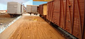
For the purposes of this tutorial, we are going to assume that you know how to due sub road bed and roadbed. I glue Homabed or strips of homasote to the plywood subiroadbed wit white glue Homabed I tack in place with extra long thumb tacks while the glue sets, and homasote I glue and screw in place using sheet rock screws.

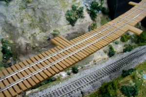
I then paint the homosote with acrylic paint to seal it. after the paint is dry I draw lines to show where the outside edges of the ties go. at switches, I draw the edges of the ties as well. In may cases I draw those in free hand, and build the switch to match. At the sawmill at the club, I am dedicated to making this area operate as well or better than the best track on the club layout. To that end I am using #6 switches throughout. I used some Atlas #6 switches as templates to mark the location of the tie ends, and the rail location at the end. In this Sawmill complex, we are planning on operating big trains. if you are wanting to run big trains, you need gentile curves, and you don't want switches with a lower number than six.


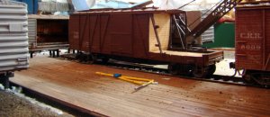
I have jigs that help me cut ties for the track. the jigs have marks on them that show approximate rail position. I stick the strip of wood in the jig, mark the rail location, and then cut the tie to size. I glue the ties on the tracks leading up to the switch first, and then glue in the switch ties.


At he location of the points, I have used a drill to drill out a slot for a manual switch actuator (on my own RR I use Minni DPST switches as ground throws, but I'm using Blue point rod actuated throws @ the club , and we will se how that goes.). Once I have the ties in for the track leading up to the switch, I cut switch ties to fit, following the outline traces off of the Atlas switch. When in doubt, I try to err on the side of a longer tie. a tie that is longer than it needs to be is no problem, and can be trimmed later for aesthetic . If your tie isn't long enough, it is a problem.

I have had problems getting uniform ballasting job done on completed track, and since there is glue on the roadbed when I glue the ties down it is a simple matter to add some ballast, and spread it with a brush . later I spray it down with wet water (water with a little dishwashing detergent added to knock out the surface tension); and flood the whole area with diluted white glue to secure the ballast.


When the glue is dry, I can lightly sand the ties, which will knock off any of the ballast that is on top of the ties, giving me a nice smooth surface to spike the rail.


I have some photos of the ballasting glue operation, but those will have to wait till tomorow, as I am turning into a pumpkin!


Bill Nelson


Edited note. old homasote would suck up moisture and hold it. thats why I used to paint it. I understand the modern stuff does not. cut off a small chunk of the homasote, and throw it in a bucket of water for a couple days. if it expands, and is heavier, you need to paint it. if you find it after a couple day, and it is not larger and heavier, it is the nes stuff, and does not need to be sealed ( guess what I paint it any way, old habits die hard!)
 
Last edited:

Bill Nelson

Well-Known Member
Dec 14, 2008
2,680
467
78
Clarksville Tn
SML blt#2.jpg SML swmltrk #1.jpg SML swmltrk #3.jpg ballasting

once the ties are in place I spread more ballast over the ties, and use a clean new paintbrush to move it around. the main goal here is to get ballast between the rails, as this is the easiest time to do it. I can add some later to the area @ the ends of the ties if I need to. NOTE: I don't put any ballast between the long ties at the points, and if any sneaks in there, it will be cleaned out with a file.

when the ballast is close I wet it with a spray bottle of wet water. I got these tiny spray bottles @ wallmart in the cosmetic department, and they work well. the idea is to get a mister. big drops of water will make craters in the ballast when they hit. Once the ballast is soaked with wet water, it stays put, and I flood the whole area with diluted white glue. the wet water on the ballast will hold the ballast in place and will suck the white glue into the ballast and will keep it in place once it is dry.

A note about ties: the Cincinnati Northern model railroad Club, where I learned to hand lay track under the direction of Terry Herweh back in the late 1960's, used pre stained ties. I have been too lazy to do this, and have stained strips of wood, and cut the ties out of it. I would then come in and stain the cut ends after the ties were glued down, but that won't work if you ballast as you put the ties down.


on this project I have cut the ties out of red cedar, and I'm gluing them down natural, with no stain, as a time saving experiment. we will see what the ties look like next week when the white glue dries. we can hope it is good, cause there is no going back and sataining them, and the thought of painting each individual tie without getting paint on the ballast does not appeal to me in the least.
 
Last edited:

Doctor G

Well-Known Member
Sep 1, 2008
1,415
298
78
Clarksville, Tennessee
Bill's bountiful bridges

In addition to Bill's beautiful hand laid track his bridges are popping up all over the club layout. Here they are in various stages of completion. Bill does great work with "sticks and glue."
Doc Tom:thumb:
 

Attachments

  • RR CLUB - 95.jpg
    RR CLUB - 95.jpg
    202.1 KB · Views: 18
  • RR CLUB - 96.jpg
    RR CLUB - 96.jpg
    199.8 KB · Views: 18
  • RR CLUB - 97.jpg
    RR CLUB - 97.jpg
    183.2 KB · Views: 18

Bill Nelson

Well-Known Member
Dec 14, 2008
2,680
467
78
Clarksville Tn
SML mckg up Br dck #1.jpg SML mckg br dck up #2.jpg SML mckg br dck up #3.jpg bridge notes

In addition to Bill's beautiful hand laid track his bridges are popping up all over the club layout. Here they are in various stages of completion.. . . . . . . Doc Tom:thumb:


As Tom points out my bridges are "popping" up every where on the club layout. When some one is building something that requires a bridge, or rehabilitating an area with a bridge, I make a big effort to make a bridge deck, both both for good looks and for good operation.


Ties on bridges are longer than, ties on regular track, and spaced closer together . For the most part , commercial track ignores this complication ( I think micro engineering makes track with bridge ties) .

also, when building a model railroad tiny variances in grade are prone to sneak in where the roadbed is cut for a bridge. On my own railroad I often will have a piece oa roadbed like wood attached to the roadbed by risers on either side of the bridge opening, making a trough deep enough to set the bridge into, so that the roadbed on the right and left of a bridge opening are tied together, to prevent getting a vertical curve on the bridge, or worse, at the ends of the bridge.

If I'm handlaying the bridge; which I prefer, to get the proper tie length, and because bridges are a natural focal point, they draw your eye. now in any spot that will be a focal point, you want to go through extra trouble to make it look as good as possible, as it will make everything around it seem better, I have the rails extend off the bridge deck, so that there is not a rail joint in the same spot where the bridge deck meets the ties supported bu the roadbed. to achieve this when the rest of the track is flex track. I take a piece of flex track, and cut the ties off the middle, where the bridge deck goes , so that a piece of flex track , integral to the bridge deck sticks out on either side , so that the rail joint is not over the bridge deck to sub road bed joint. Similarly when you are building your bench work, don't have a joint between frame members, sub roadbed, roadbed or rail at the same location. Stagger your joints, and you will be less likely to have any errors compound into something that causes you operational problems.

If I'm replacing some track with a bridge, I put blank paper over the section of track and make a rubbing with a crayon, that shoes me the rail location exactly. I then mark the exact location of the beginning and the end of the bridge, and cary that paper to my work board (a piece of homasote). I put the paper on the work board, cover it with a piece of wax paper, and pin them both in place with thumb tacks.

If I'm making a bridge deck with three stringers, the center stringer follows the rail head exactly. If I'm building a bridge deck with two larger stringers, the rail will follow the joint between them. the stringers are glued together with tacky glue directly on the wax paper, which will usually peel right off, although sometimes pieces will stick and have to be scraped off. Usually I do this with wood that has been pre-stained. this bridge I'm building out of unstained red cedar pit of ( #1 laziness or #2 deep respect for the color, tone and texture of the natural material -- you choose) ince the stringer assembly, with spacers to keep them just the right distance apart, I remove them from the wax paper, and lightly sand them to remove any bumps, so the bridge ties will lay flat. if the wood is pre stained it gets stained again after it is sanded. Lots of work, but the results are worth it. people will look at the bridge more than they look at the stuff around the bridge, let's not dissapont them!

Next the ties will get cut and installed. The ties appear to be too big in cross section , but the width was selected to match the ties on the nearby atlas flex track, and the height was cut the same, as the saw fence was already set in that position, and if I have the tie dimensions very close, but not exactly the same, I find I'm always gluing some of them down oriented incorrectly.


That is just about it for today's program, next I will show how I set up a tie marking and cutting jig, which will allow me to get bridge ties uniformly marked with the rail location, and cut to a uniform size.

Tom, on Monday we will be ready to lightly sand the ties, enough to knock off any ballast that is above the tie level, but not enough (we desperately hope) to erase the pencil lines that suggest rail location. We might be spiking some rail! We also need to be prepared to start scenery on the banks of the log pond under where the bridge to the Cumberland #1 mine complex. Tom be warned! I'm not going to permit scenery materials extending above the level of the homasote any where near my re cedar ties. That always looks sloppy, and we have had to , on the long grade to the upper level, chisel some of those off to keep the steps on diesels from contacting them. In any case the whole point of ballast is to allow drainage around the ties, and for this to happen the track has to be above the level of the scenery. As much work as I am putting into the track work, I'm going to be pushing for neater cleaner work in every way shape or form in the sawmill complex. This is part of the plan , To improve the workmanship in this area, so that it looks better, and runs better than anywhere else at the club, sadly not as big a challenge as it should be.

So be warned on my track work, and the scenery in this area, I'm going to be a picky ********, and may be even less pleasant to be around than usual.

Bill Nelson
 
Last edited:

Bill Nelson

Well-Known Member
Dec 14, 2008
2,680
467
78
Clarksville Tn
SML brdg tie jig .jpg secial bridge tie jig

these bridge ties are longer than usual, as they are in a switching area I want them to be long enough to where crewmen can walk alongside a stopped train across the bridge. because of this, the tie jigs I have made for other bridges wouldn't work, so I had to make another.

Note at the end of the jig there is an extra piece of wood glued on top og the jig so the jig sets up above the tie to be cut. this keeps someone in a hurry , or who doesn't have thier reading glasses on from romoving the end of the gig shortining not only that ties but every subsequent tie as well.

the pencil lines show the location of the rails.


Bill Nelson
 
Last edited:

Bill Nelson

Well-Known Member
Dec 14, 2008
2,680
467
78
Clarksville Tn
click on that thubnail to get a larger vier. in the latger yiew you can see the pencil marks that locate the rail marks, and the dots that will allow me to line the ties up on the stringers the same way, so everything will be rxtra neat.

Bill Nelson