I tried figuring out a couple of the track planning software programs, but could not get them to behave. So I bought the KISS system. Plastic circles for hand drawing. I drew up a plan and then built my bench.
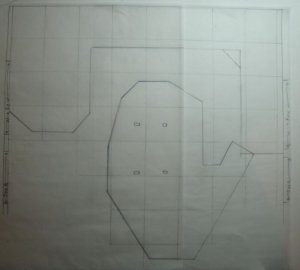
Now I am looking closer at my plan and think that I may have a number of problems. The 'table_diagram' is draw on 2 ft squares and I used 24" main line curves. My plan is to stay less then 2% grades. This an HO layout and it is my second RR. The first one was over 30 years ago and was 8X4 ft sheet of plywood.
The bench work goes around the wall in a U shape and then connects to the island in the middle of the room. You can walk around the island and between the table along the wall and the island. The island is 7 inches higher than the bench work along the wall.
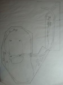
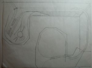
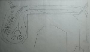
Looking at the image you can see that I placed a 4 track freight yard in the middle and the passenger yard with engine services on the left wall. The track would start increasing in elevation as it goes around the left wall section and be about 2 inches higher when it becomes double main line behind the freight yard. There would be a gully at the right corner of the wall section as the track continued to raise. I'll need to build a trestle to make this transition. The track will have reach the 7" rise by the time it gets to the island section.
The island will have a mountain in the middle do the double main line enters the mountain by one large tunnel and out the other side by two smaller tunnel exits. Track continues to elevate enough to cross back over the line entering the island and then drops back to match the other side of the double main line and the back down the hill.
I have drawn a few freight business along the main line.
If this is not clear I will try to explain better.
Now to my questions:
I am concerned that the curve out the the freight yard that goes around the passenger terminal (the main line) will not allow correct easements and have room for a straight section between the two curves. This is the dreaded S curve problem.
Also I don't how I would operated the passenger train with this arrangement. Assuming that I just came into town on the main line, I would need to pull into the freight yard and then back into the terminal. So far so good. Now the passengers load. How do I get the train going back around the main loop? The engine is on the wrong end, which I could fix by running it around and turning on the turntable. But what do I do about the observation car?
Any help would be greatly appreciated. If I need to abandon this plan, then so be it. My goals are to have a long main line so that I could watch the train run through scenery. I want some switching work too. At some point I think that I may expand the layout to go around the island mountain and then back along the wall on an upper deck and then back to the island across a duck under bridge next the passenger yard part of the layout. I might put in some logging operation on the upper deck (above the mountain on the island).
Kent
Now I am looking closer at my plan and think that I may have a number of problems. The 'table_diagram' is draw on 2 ft squares and I used 24" main line curves. My plan is to stay less then 2% grades. This an HO layout and it is my second RR. The first one was over 30 years ago and was 8X4 ft sheet of plywood.
The bench work goes around the wall in a U shape and then connects to the island in the middle of the room. You can walk around the island and between the table along the wall and the island. The island is 7 inches higher than the bench work along the wall.
Looking at the image you can see that I placed a 4 track freight yard in the middle and the passenger yard with engine services on the left wall. The track would start increasing in elevation as it goes around the left wall section and be about 2 inches higher when it becomes double main line behind the freight yard. There would be a gully at the right corner of the wall section as the track continued to raise. I'll need to build a trestle to make this transition. The track will have reach the 7" rise by the time it gets to the island section.
The island will have a mountain in the middle do the double main line enters the mountain by one large tunnel and out the other side by two smaller tunnel exits. Track continues to elevate enough to cross back over the line entering the island and then drops back to match the other side of the double main line and the back down the hill.
I have drawn a few freight business along the main line.
If this is not clear I will try to explain better.
Now to my questions:
I am concerned that the curve out the the freight yard that goes around the passenger terminal (the main line) will not allow correct easements and have room for a straight section between the two curves. This is the dreaded S curve problem.
Also I don't how I would operated the passenger train with this arrangement. Assuming that I just came into town on the main line, I would need to pull into the freight yard and then back into the terminal. So far so good. Now the passengers load. How do I get the train going back around the main loop? The engine is on the wrong end, which I could fix by running it around and turning on the turntable. But what do I do about the observation car?
Any help would be greatly appreciated. If I need to abandon this plan, then so be it. My goals are to have a long main line so that I could watch the train run through scenery. I want some switching work too. At some point I think that I may expand the layout to go around the island mountain and then back along the wall on an upper deck and then back to the island across a duck under bridge next the passenger yard part of the layout. I might put in some logging operation on the upper deck (above the mountain on the island).
Kent