Renova CSS Hunley
When I learned this model was released I just had to have one (actually two). I have a couple of other resin kits but they are somewhat inaccurate. Renova’s kit seems to be based on the latest information available. I live about about 5 hours from Charleston, SC and have seen the Hunley under restoration. So, it was with great anticipation that I began this project.
You will find my text keyed to numbered photos as if you were reading a zine article. Also, I will share some equipment choices and techniques with you. Though I cannot design like some of our more prolific forum members, I have a varied base of experience in materials, techniques, and processes to share. Though I have started this as a naval thread, you will see I used techniques applicable to other subject areas, too.
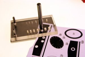
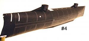
Photo #1 Eschewing the shot of the packaging and parts, I’ll start straight with the build. First, I have seen reported a number of problems with 1mm cardstock warping. The simple answer is to stop using the 1mm cardstock we routinely associate with paper modeling and switch to mechanical board, sometimes called “illustration board.” Go to dickblick.com and search for “LetraMax 2000 mechanical board.” It will cost about $7.00 plus shipping for a sheet 30” x 36” that will last many models. Save shipping and go to your local art supply house. The product does not warp. In fact, I have a supply that I have been carrying around the world since the middle 80’s that suffered a bit of water damage recently. The area not affected is perfectly fine; in fact, I used it for this project. It measures a tad over 1mm thick and can be delaminated. However, under regular use, it does not delaminate, fray or exhibit any of the undesirable qualities normally associated with cardstock. I assembled the bulkheads with Tacky Glue. Notice that the edges of the bulkheads are colored. You’ll learn why shortly.
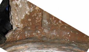
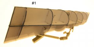
Photo #2 In a departure from normal building procedure and taking a cue from the RC guys, I am cutting sections of closed-cell Styrofoam to size to fit the spaces between the bulkheads. I use the foam in which computers are packed. It is light, dense, and very strong. I am using the “Hot Wire Foam Factory” kit which includes a number of useful accessories to cut the foam. The heated nichrome wire cuts through foam like, well, a hot knife through warm butter.
Precision is the watchword here. I want the foam to fit exactly. If I cut too small, I have to backfill the gaps (acrylic spackle); too large and I force the bulkheads out of square. Fortunately, the hot wire technique is so precise that I can shave off pieces that are a few thousandths of an inch thick if the need arises.
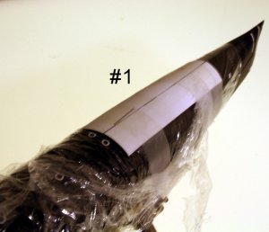
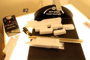
Photo #3 This close-up shows that I have ensured the wire is square with the table. Additionally, I use a draftsman ruler as a fence to ensure precise and constant cuts. Any straight-edge will do. You can make your own hot wire cutter with some wood, a motorcycle battery and 30AWG nichrome wire purchased over the Internet.
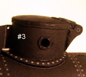
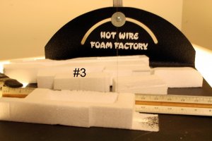
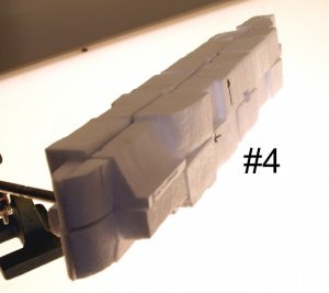
Photo #4 Using Elmer’s White glue (PVA glue) to adhere Styrofoam, this is what the hull looks like. It took a few hours to do this, working continuously, but you are going to see that this extra effort up front is going to pay off in spades later!
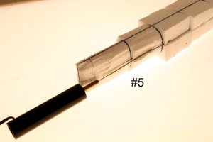
Photo #5 Using one of the accessories in the Hot Wire kit, I am roughly removing the excess Styrofoam using the bulkheads as a guide.
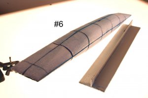
Photo #6 With an aluminum T-bar and 50 grit sandpaper, I roughed the Styrofoam down and finish sanded with 180 grit. This is where the colored bulkheads come in handy. The second I touch and edge, the color comes away indicating the limit of my sanding. Once complete, the hull is rigid.
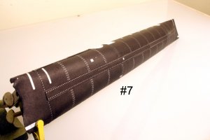
Photo #7 The reason for the Styrofoam is three-fold; first, it gives me a solid surface onto which I can glue the hull plates WITHOUT backing strips. Second, the foam undersurface prevents sagging of the paper between bulkheads. Real ships do show evidence of this but usually only after sea duty. Nevertheless, in the scales we build, that sagging is really over stated. Finally, having a solid hull allowed me to really muscle the paper into place minimizing any seams. I used some simple tools, mainly a wooden ruler, to make sure adjacent seams were perfectly flush with each other. The foam carried the load!
More importantly, the Hunley was flush riveted and quite smooth. I didn’t want to see bulkhead bulges and sagging plates.
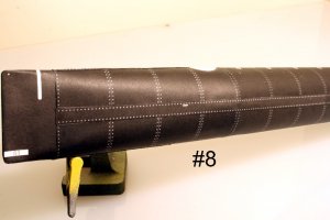
Photo #8 The proof is in the pudding. There are several seams here. Judge for yourself. This technique actually saved time and effort. I completely covered the hull in about 5 hours, taking my time and carefully aligning hull plates.
General notes:
1. The Renova CSS Hunley is excellent value for the money!
2. The parts fit is superb, in particular the hull plates.
3. There are three main plates in addition to bow and stern plates. Each plate is designed as one wrap-around piece. I recommend cutting each main plate into an upper and lower plate. It is easier to adhere and align them this way. The bow and stern plates are best assembled as is. Their fit is almost perfect requiring just a little filler material.
4. Speaking of filler material, the kit includes extra black and copper color sections for any eventuality that might arise. I used a bit of the black to fill in areas not completely covered by the bow and stern plates.
5. God willing and the creek don’t rise, I’ll have her complete in a couple of weeks for your perusal.
Regards!
When I learned this model was released I just had to have one (actually two). I have a couple of other resin kits but they are somewhat inaccurate. Renova’s kit seems to be based on the latest information available. I live about about 5 hours from Charleston, SC and have seen the Hunley under restoration. So, it was with great anticipation that I began this project.
You will find my text keyed to numbered photos as if you were reading a zine article. Also, I will share some equipment choices and techniques with you. Though I cannot design like some of our more prolific forum members, I have a varied base of experience in materials, techniques, and processes to share. Though I have started this as a naval thread, you will see I used techniques applicable to other subject areas, too.
Photo #1 Eschewing the shot of the packaging and parts, I’ll start straight with the build. First, I have seen reported a number of problems with 1mm cardstock warping. The simple answer is to stop using the 1mm cardstock we routinely associate with paper modeling and switch to mechanical board, sometimes called “illustration board.” Go to dickblick.com and search for “LetraMax 2000 mechanical board.” It will cost about $7.00 plus shipping for a sheet 30” x 36” that will last many models. Save shipping and go to your local art supply house. The product does not warp. In fact, I have a supply that I have been carrying around the world since the middle 80’s that suffered a bit of water damage recently. The area not affected is perfectly fine; in fact, I used it for this project. It measures a tad over 1mm thick and can be delaminated. However, under regular use, it does not delaminate, fray or exhibit any of the undesirable qualities normally associated with cardstock. I assembled the bulkheads with Tacky Glue. Notice that the edges of the bulkheads are colored. You’ll learn why shortly.
Photo #2 In a departure from normal building procedure and taking a cue from the RC guys, I am cutting sections of closed-cell Styrofoam to size to fit the spaces between the bulkheads. I use the foam in which computers are packed. It is light, dense, and very strong. I am using the “Hot Wire Foam Factory” kit which includes a number of useful accessories to cut the foam. The heated nichrome wire cuts through foam like, well, a hot knife through warm butter.
Precision is the watchword here. I want the foam to fit exactly. If I cut too small, I have to backfill the gaps (acrylic spackle); too large and I force the bulkheads out of square. Fortunately, the hot wire technique is so precise that I can shave off pieces that are a few thousandths of an inch thick if the need arises.
Photo #3 This close-up shows that I have ensured the wire is square with the table. Additionally, I use a draftsman ruler as a fence to ensure precise and constant cuts. Any straight-edge will do. You can make your own hot wire cutter with some wood, a motorcycle battery and 30AWG nichrome wire purchased over the Internet.
Photo #4 Using Elmer’s White glue (PVA glue) to adhere Styrofoam, this is what the hull looks like. It took a few hours to do this, working continuously, but you are going to see that this extra effort up front is going to pay off in spades later!
Photo #5 Using one of the accessories in the Hot Wire kit, I am roughly removing the excess Styrofoam using the bulkheads as a guide.
Photo #6 With an aluminum T-bar and 50 grit sandpaper, I roughed the Styrofoam down and finish sanded with 180 grit. This is where the colored bulkheads come in handy. The second I touch and edge, the color comes away indicating the limit of my sanding. Once complete, the hull is rigid.
Photo #7 The reason for the Styrofoam is three-fold; first, it gives me a solid surface onto which I can glue the hull plates WITHOUT backing strips. Second, the foam undersurface prevents sagging of the paper between bulkheads. Real ships do show evidence of this but usually only after sea duty. Nevertheless, in the scales we build, that sagging is really over stated. Finally, having a solid hull allowed me to really muscle the paper into place minimizing any seams. I used some simple tools, mainly a wooden ruler, to make sure adjacent seams were perfectly flush with each other. The foam carried the load!
More importantly, the Hunley was flush riveted and quite smooth. I didn’t want to see bulkhead bulges and sagging plates.
Photo #8 The proof is in the pudding. There are several seams here. Judge for yourself. This technique actually saved time and effort. I completely covered the hull in about 5 hours, taking my time and carefully aligning hull plates.
General notes:
1. The Renova CSS Hunley is excellent value for the money!
2. The parts fit is superb, in particular the hull plates.
3. There are three main plates in addition to bow and stern plates. Each plate is designed as one wrap-around piece. I recommend cutting each main plate into an upper and lower plate. It is easier to adhere and align them this way. The bow and stern plates are best assembled as is. Their fit is almost perfect requiring just a little filler material.
4. Speaking of filler material, the kit includes extra black and copper color sections for any eventuality that might arise. I used a bit of the black to fill in areas not completely covered by the bow and stern plates.
5. God willing and the creek don’t rise, I’ll have her complete in a couple of weeks for your perusal.
Regards!
")