Turntable

mentor63

New Member
Jan 29, 2008
59
0
6
Colorado Springs, CO
Well, I took the plunge and cut the hole for the turntable tonight. I had to re-do some benchwork since it ended up being in a slightly different place than I had planned originally. Also the clearance required below the TT necessitated cutting out some areas from supporting benchwork. I think it turned out pretty well. Now that I have that done, placement of the roundhouse is the next key issue to get the geometry correct. I am more concerned about that , at this point, than the operation of the turntable.

Onward and upward.

Mentor63
 

mentor63

New Member
Jan 29, 2008
59
0
6
Colorado Springs, CO
Ok, I'll give it a try, but I will have to break the computer code first.

I think I have it. This is a photo of the Walthers 130' turntable sitting in the hole with the surrounding holes drilled for the mounting stubs under and around the perimeter so it sits flat (can't see the stubs as they are under the lip of the TT). I checked and everything is nice and level. The optical "zero" sensor is at about 11 o'clock and the "no track here" area is indicated by the black lines at about 8 and 2 o'clock with 12 o'clock being at the far side of the pit for the purposes of this photo.

utilityroom 273.jpg

This shows two issues. 1) the ties are not removed from the tracks leading from the roundhouse so they are on the lip of the TT which results in the front of the roundhouse being slightly off the surface (when ties are removed it should sit flat), and 2) the inspection pit(s) are about 3/8" in depth and they are mounted to the bottom of the RH floor. The plans say nothing about this except to glue them in place, but it seems clear to me that I need to cut out openings for these below the round house. Am I missing something here? I am assuming the roundhouse sits directly on the plywood.

utilityroom 276.jpg

These are just extras since I have broken the code. My layout is two levels at 36" and 54" with a transition climb that goes around the finished utility room 1 1/2 times to go from one level to the other (about 2% grade). I have crammed a lot into a fairly small space (14' x 16') so I know the isles are way too narrow, but I have been able to keep all the track curves pretty close to 24" and I felt that was a bigger priority since I don't expect to have more than 2-3 people in the area at a time. I added some surface area to the right of the rear of the RH since I took this photo so trains are not close to the edge. I am thinking about adding a clear plexiglass fence also to extend 2"-3" higher than the fascia. None of that is ideal, but I think I have to for functionality.

utilityroom 225.jpg
utilityroom 229.jpg

More later. Keep flying with the eagles!

Mentor63
 
This shows two issues. 1) the ties are not removed from the tracks leading from the roundhouse so they are on the lip of the TT which results in the front of the roundhouse being slightly off the surface (when ties are removed it should sit flat), and 2) the inspection pit(s) are about 3/8" in depth and they are mounted to the bottom of the RH floor. The plans say nothing about this except to glue them in place, but it seems clear to me that I need to cut out openings for these below the round house. Am I missing something here? I am assuming the roundhouse sits directly on the plywood.

First off - Look'in good! Second yes the round house sits on the plywood and yes you have to cut holes for the inspection pits.

It this the TT with indexing? If so how does it work? I think I want to purchase the same one. I've been putting it off but this would be the only one that would support big steam.
 

mentor63

New Member
Jan 29, 2008
59
0
6
Colorado Springs, CO
Trainiac77,
Yes, it is the indexing TT. I have not completed that part of the installation, but this is basically what the instructions say.

It is all controlled by a box about 4" x 4" x 1" which I will probably mount on the fascia near the TT. It is connected to the center of the TT on the bottom by a fairly heavy, computer type cable. The box has a button which "zeros" the system to an optical sensor. That initializes the TT position before programming track positions. It can also be used later to re-initialize the system if it gets off a bit. With that done, you then push an arrow on the same box to move the TT right or left until it is where you want it. At that point you push a "Set" button on the same box and that programs it to remember where that set of tracks is located.

You need to program each track this way. When complete, you simply push the arrow in the direction you want the TT to turn and release it when it approached the desired track (it does not have separate buttons for track 1, 2, 3, etc.). Sounds simple, huh? It says you can delete a track setting if needed and you can program up to 60 locations. Everything seems to come with it except for the 15v power supply (12 to 19v is acceptable I think it said). As far as how it works, I don't really know the technical answer, but when I was flying jets we used to call this kind of stuff "FM" for flaming magic. As long as it works, that was the main thing.

Hope that helps. Good luck if you decide to get one.

Mentor63
 

60103

Pooh Bah
Mar 25, 2002
4,754
0
36
Brampton, Ontario, Canada
Visit site
mentor63: you probably should have a pit in each track in the roundhouse, unless some of the are for non-repair purposes. But check if you can actually see them before you start work.
Chooch and Peco make pits with steps. Peco's is a bit more complete ut Chooch might be more easily available in the US. You still have to carve a big slot in the plywood.
 

mentor63

New Member
Jan 29, 2008
59
0
6
Colorado Springs, CO
Thanks for the info, Pooh Bah. As I get close to completing the track I feel more and more like I am about to paint mayself into a corner since everything has to fit with everything else now. Not much room for adjustments. I hope I don't run into too many more surprises. On the other hand it is all fun and I am getting better at recovering from mistakes on the layout.
 

mentor63

New Member
Jan 29, 2008
59
0
6
Colorado Springs, CO
Well, it has been about a week since I added anything so I thought I would post an update.

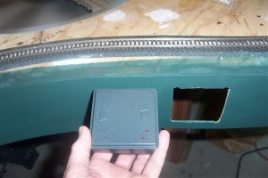
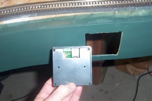
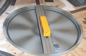
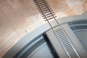
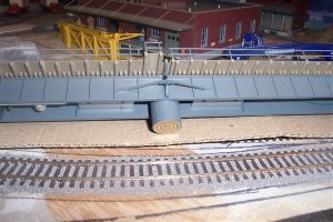
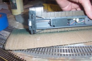
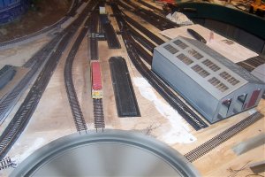
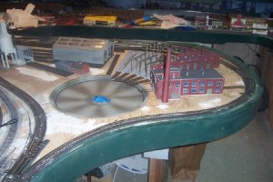
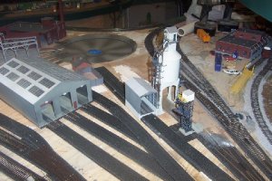
Once I got the turntable in the hole and the roundhouse scoped out, I realized I still had a lot of heavy lifting to do (cutting holes, using glues, laying track, completing fascia, etc.) and I did not what to do that after fine tuning the turntable. So I have spent the last week cutting the holes for the inspection pits under the roundhouse (per Trainiac77), cutting the inspection pits for the diesel area, completing the fascia, laying roadbed, track and turnouts in the area around this area and test fitting structures for the area. I also had to build ramps to lower two approach tracks from roadbed to tabletop to be at the correct height when they reach the TT and I built an upramp for the gondolas that service the cinder tower, coal tower and sand area. In the process I reduced the roundhouse to 5 stalls, added a track for the second coal tower chute (I had forgotten about), assembled the sanding facility so I could make sure it would fit and I am just finishing kitbaching the diesel sanding rack from 24" to under 12". The upshot is that I have all the roadbed in and all except about 10' of the track in. Also, I found that the screws that come with the Walthers 130' TT are a bit short since I used wood that is slightly over 1/2" thick so I had to send off for some longer ones. When they arrive I should be ready to secure the TT and start adding the tracks that lead to it. Oh, yes, I also decided to rotate the TT 90 degrees to avoid any problems with the "no track here" areas which were a bit close to one of my intended approach tracks. Attached are a couple of photos of the progress. More later.
 

Attachments

  • utilityroom 280.jpg
    utilityroom 280.jpg
    105.8 KB · Views: 20
  • utilityroom 284.jpg
    utilityroom 284.jpg
    132.3 KB · Views: 14

green_elite_cab

Keep It Moving!
Apr 4, 2005
1,876
0
36
34
Hainesport NJ
Cool!I've always been an aviation buff before trains (although model airplanes have until recently been ot irratating for me to get right. Dang those seams in the wings!). I've always wanted to fly, although it looks like all the cool stuff is in the military.

anyways, awesome roundhouse/turntable!
 

mentor63

New Member
Jan 29, 2008
59
0
6
Colorado Springs, CO
Well, I got the securing screws in the bottom of the TT and cut the hole for the control box in the fascia. That went ok except the cable connection has to be at the top of the box and there is no room above the hole so I plan to mount it by rotating it 90 degrees so the cable and wires connect on the side, not the top. See photos below.

So I am now at the point where I will be laying the track leading to the turntable. The instructions say TT drive can use 12-19VAC, but recommends dedicated 15 VAC for the motor drive in the unit. I have an old transformer I could use, but it is noisy so I am going to see if Radio Shack has something that would be better.

In the last photo you can see in the bottom of the TT pit the small teeth that determine where the TT will stop. It looks like it will stop about every 1/32" to align with the incoming track, but only 60 stops can be progammed (which is more than I could possibly use). Hopefully you can also see that the bridge track railhead is filed to a point where is meets the incoming track. The incoming track should stop at the lip of the TT, which leaves about 1/16" gap between it and the TT track. Also the incoming track needs to be filed like the bridge track. This effectively makes the track wider where they meet and improves the transfer from one to the other (according to the instructions).

As I get into this I am gaining confidence and it is really easier than I expected...so far. More later, Gary
 

Attachments

  • utilityroom 292.jpg
    utilityroom 292.jpg
    136.7 KB · Views: 37
  • utilityroom 293.jpg
    utilityroom 293.jpg
    132.9 KB · Views: 57
  • TTBridge.jpg
    TTBridge.jpg
    51.1 KB · Views: 9
  • utilityroom 291.jpg
    utilityroom 291.jpg
    134.4 KB · Views: 28
So I am now at the point where I will be laying the track leading to the turntable. The instructions say TT drive can use 12-19VAC, but recommends dedicated 15 VAC for the motor drive in the unit. I have an old transformer I could use, but it is noisy so I am going to see if Radio Shack has something that would be better.

The install looks like it's going great! One of these days I'm going to purchase one of those TT's as well.

I found this link for a 15 volt VAC transformer From ALL Electronics:
A.C. Wall Transformers

It usually takes a week to get the items but sometimes it's worth the wait. Hope it helps!
icon7.gif
 

mentor63

New Member
Jan 29, 2008
59
0
6
Colorado Springs, CO
Trainiac77,

Thanks for the tip. I did not find what I needed at Radio Shack so maybe this will do the trick.

Yesterday I got three service tracks installed leading to the TT. I had to install the cinder pit and tower first as it goes under one of the service tracks. I also glued all 5 inspection pits to the bottom of the roundhouse stall floors.

Today I cut and filed the tracks for 3 roundhouse stall floors as discribed above. The geometry and fit are not very forgiving since the tracks going into the roundhouse are all fixed in the stall floors and must be positioned so all 5 tracks meet at the center of the TT pit. Getting individual tracks aligned was much easier.

Then I noticed that a track which will lead to the TT was still on roadbed about a foot from the TT so I started building a ramp to get it down to layout level to match the TT lip. I also rechecked the TT for level and found it slightly unlevel so I used some shims between the bottom of the layout plywood and the benchwork to get it level.

More later, Gary
 

mentor63

New Member
Jan 29, 2008
59
0
6
Colorado Springs, CO
I made a little more progress today. Did a lot of electrical feeders and finished the ramp leading down to the TT from the roadbed level. One issue I am running into is that the pit is a real dust collector and should probably be covered most of the time as the instructions make a point about dust and dirt being a problem.

Attached are some photos for anyone thinking about a Walthers 130' TT. The first one shows the bottom of the bridge center post. You can see the metal contact rings. The second photo shows the pit center hole and the metal finger contacts which contact the contacts shown in the first photo. The third photo shows the bottom of the bridge. It is a bit fuzzy, but hopefully you can make out the wires from the center post to the drive motor and the drive shaft to the white, toothed, wheel which moves the bridge. The drive is only on one end of the bridge. Both ends have small black plastic wheels which just support the bridge.

The last photo is just a general overview. Thanks for the inputs. More late. Gary
 

Attachments

  • utilityroom 294.jpg
    utilityroom 294.jpg
    203.2 KB · Views: 7
  • utilityroom 296.jpg
    utilityroom 296.jpg
    75.2 KB · Views: 10
  • utilityroom 295.jpg
    utilityroom 295.jpg
    142.8 KB · Views: 13
  • utilityroom 297.jpg
    utilityroom 297.jpg
    197.7 KB · Views: 63

Fluesheet

Member
Jan 22, 2006
339
0
16
Central Ohio
mentor, thanks for the detail photos above. I'm looking for a TT as well, but had assumed that all powered ones were done so via the shaft. The Walthers solution is interesting and simple. I'm curious as to how reliable those contact wipers will be over the long term.

Good luck on the remainder of the project!

Fluesheet.